Light-emitting diode (LED) heat radiation structure

A technology of LED light source and heat sink, applied in lighting and heating equipment, cooling/heating device of lighting device, lighting device, etc., can solve the problems of chip light aging, hot hand, small light angle, etc. High heat dissipation efficiency and the effect of eliminating light leakage

Inactive Publication Date: 2013-02-06
谭永安
View PDF6 Cites 0 Cited by
  • Summary
  • Abstract
  • Description
  • Claims
  • Application Information

AI Technical Summary

Problems solved by technology

Most LED light source products have the following problems in terms of heat dissipation and light efficiency: 1. The unreasonable heat dissipation structure of the product leads to the short life of the drive circuit and premature light decay of the chip, which affects the product life cycle
2. The design of the chip position is unreasonable, resulting in too small light angle, and the product application has not been able to replace traditional incandescent lamps and energy-saving lamps in a real sense.
3. Too many exposed metal heat sinks lead to safety hazards such as hot hands and easy electric shocks during use

Method used


Image

  • Light-emitting diode (LED) heat radiation structure
  • Light-emitting diode (LED) heat radiation structure

Examples


Embodiment Construction

[0012] The preferred embodiments of the present invention are given below in conjunction with the accompanying drawings to describe the technical solution of the present invention in detail.

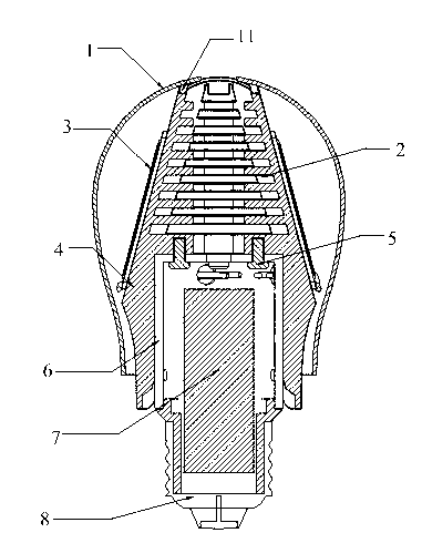
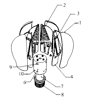
[0013] Such as figure 1 with figure 2 As shown, the LED light source structure of the present invention includes a translucent milky white lampshade 1, four heat sinks 2, an LED chip 3, an aluminum alloy die-casting part 4, screws 5, a protective cover 6, a driving circuit board 7, a lamp holder 8, and wiring holes 9 , air vent 10, heat sink 2, LED chip 3, aluminum alloy die-casting 4, and screw 5 are all located in the translucent milky white lampshade 1, LED chip 3 is located on the front of the aluminum alloy die-casting 4, and heat sink 2 is located in the aluminum alloy die-casting In the part 4, the angle between the LED chip 3 and the horizontal plane is 75 degrees, the protective cover 6 and the aluminum alloy die-casting part 4 are fixed by screws 5, the protective cover 6 wra...


PUM


Abstract

The invention discloses an LED heat radiation structure. The heat radiation structure comprises a semitransparent milk-white lamp shade, four radiating fins, an LED wafer, an aluminium alloy pressure casting, a screw, a protective sleeve, a driving circuit board and a lamp holder, wherein radiating fins, the LED wafer, the aluminium alloy pressure casting and the screw are arranged inside the semitransparent milk-white lamp shade, the LED wafer is located on the front face of the aluminium alloy pressure casting, radiating fins are located inside the aluminium alloy pressure casting, an angle of 75 degrees is formed between the LED wafer and the horizontal plane, the protective sleeve and the aluminium alloy pressure casting are fixed through the screw, the protective sleeve covers the upper portion of the driving circuit board, the lamp holder is fixed below the driving circuit board, four radiating fins do not contact with one another directly and are independent cooling modules, and a notch is reserved at the top end of the aluminium alloy pressure casting. According to the LED light source structure, the heat radiation efficiency is improved, and light angles of products are increased.

Description

technical field [0001] The invention relates to a light source structure, in particular to an LED heat dissipation structure. Background technique [0002] As an emerging lighting technology, LED is used in light source products to replace traditional incandescent lamps and energy-saving lamps. Most LED light source products on the market do not really meet the requirements of replacing traditional light sources in terms of technical parameters such as light angle and luminous flux. Therefore, the purpose of this product technology research and development is to make the product truly meet the requirements of replacement. Most of the LED light source products on the market can be classified into the following types: first, the upper part of the product is the light-emitting part of the chip component and the PC translucent lampshade, and the lower part is the heat dissipation part of the whole product (generally made of aluminum parts and Die-casting aluminum parts) and lam...

Claims


Application Information

Patent Timeline
Patent Type & Authority Applications(China)
IPC IPC(8): F21V29/00F21Y101/02F21V29/70F21Y115/10
Inventor 梁锐锋谭永安
Owner 谭永安
Why Eureka
Try Eureka