A kind of automatic assembly equipment of cylindrical helical spring resistance element

A resistance element and helical spring technology, which is applied in the field of automatic assembly equipment for cylindrical helical spring-shaped resistance elements, can solve the problems of low assembly efficiency, difficulty in ensuring product quality, and high intensity of manual assembly work, achieving convenient operation, reducing labor costs, The effect of improving operational efficiency and product quality

Inactive Publication Date: 2015-08-19
深圳市华力特电气有限公司
View PDF4 Cites 0 Cited by
  • Summary
  • Abstract
  • Description
  • Claims
  • Application Information

AI Technical Summary

Problems solved by technology

[0003] First: The tightness of the hand-assembled cylindrical helical spring-like resistance element and the porcelain tube cannot be guaranteed; different people or the same person assemble the cylindrical helical spring-like resistance element under different physical conditions, and the cylindrical helical spring-like resistance element and the porcelain tube There are differences in the tightness of the fit;
[0004] Second: The high intensity of manual assembly results in low assembly efficiency; manual assembly of cylindrical helical spring-shaped resistance elements and porcelain tubes can only assemble about 5 pieces per hour per person, and the efficiency is very low, which is far from meeting the needs of normal production;
[0005] Third: As the strength of manual assembly cannot be guaranteed to be consistent, the cylindrical helical spring-like resistance element may be too elongated or too short to be assembled on the porcelain tube, resulting in frequent rework and difficult to guarantee product quality

Method used


Image

  • A kind of automatic assembly equipment of cylindrical helical spring resistance element
  • A kind of automatic assembly equipment of cylindrical helical spring resistance element
  • A kind of automatic assembly equipment of cylindrical helical spring resistance element

Examples


Embodiment Construction

[0043] An embodiment of the present invention provides an automatic assembly device for cylindrical helical spring-shaped resistance elements, which is used for automatic assembly of cylindrical helical spring-shaped resistance elements, improving operating efficiency and product quality

[0044] The following will clearly and completely describe the technical solutions in the embodiments of the present invention with reference to the accompanying drawings in the embodiments of the present invention. Obviously, the described embodiments are only some, not all, embodiments of the present invention. Based on the embodiments of the present invention, all other embodiments obtained by persons of ordinary skill in the art without creative efforts fall within the protection scope of the present invention.

[0045] Each will be described in detail below.

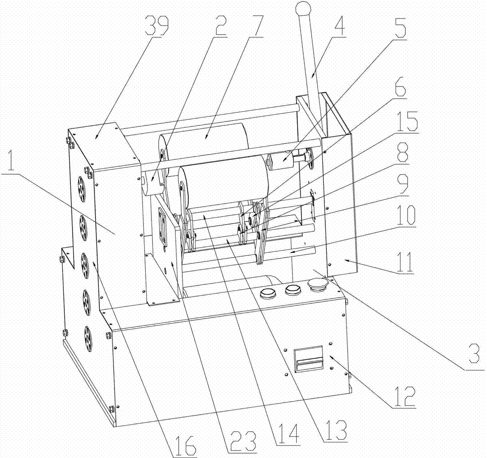
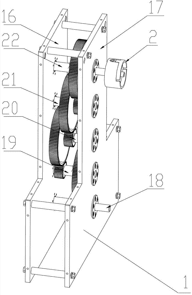
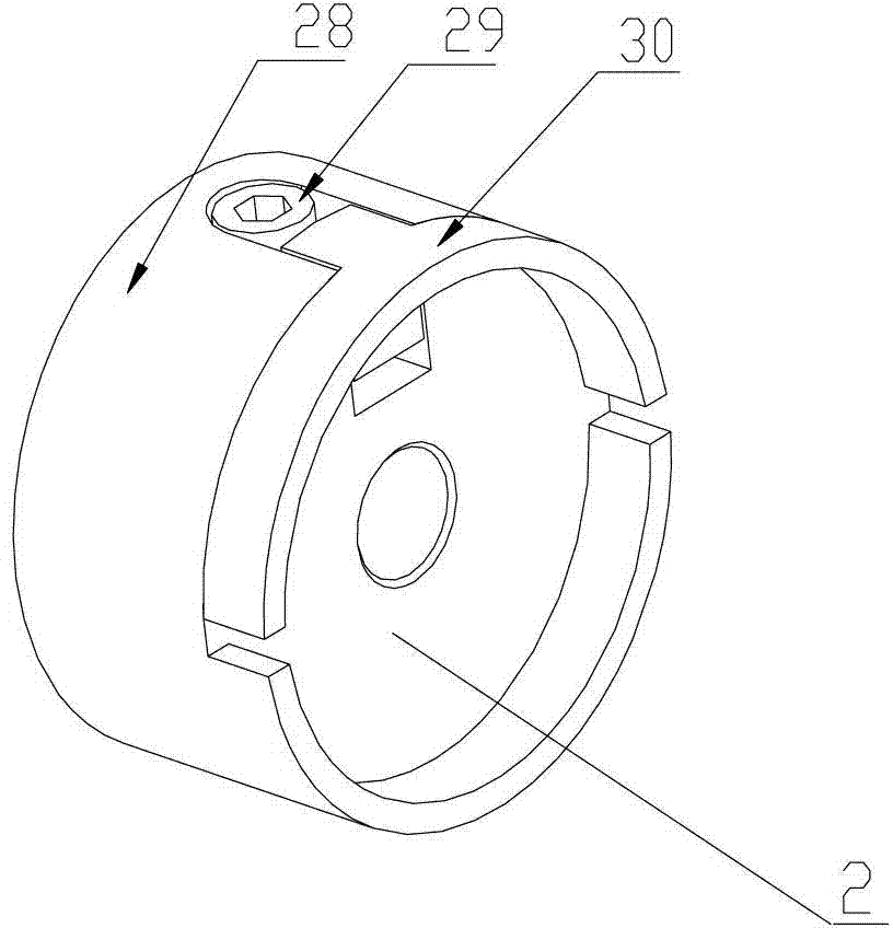
[0046] Please refer to figure 1 , figure 1A schematic diagram of the overall structure of an automatic assembly equipment for a...


PUM


Abstract

The embodiment of the invention discloses automatic assembling equipment for a cylindrical helical spring-like resistor element. The automatic assembling equipment for the cylindrical helical spring-like resistor element is used for automatically assembling the cylindrical helical spring-like resistor element, which can improve the operating efficiency and the product quality. The automatic assembling equipment for the cylindrical helical spring-like resistor element comprises a driving mechanism, ceramic tube clamping mechanism and a resistor element clamping mechanism, wherein the driving mechanism comprises an input shaft, a gear shaft and an output shaft, and is used for driving a ceramic tube clamped on the ceramic tube clamping mechanism to rotate under the driving of a brake motor through the input shaft, the gear shaft and the output shaft which are connected with the brake motor; the ceramic tube clamping mechanism is connected with the output shaft; the ceramic tube clamping mechanism is used for clamping the ceramic tube; the resistor element clamping mechanism has a multi-connecting rod structure and is used for driving connecting rods to move under the pushing of an operating rod; and under the rotation of the ceramic tube clamping mechanism, the cylindrical helical spring-like resistor element is wound and pressed on the surface of the clamped ceramic tube.

Description

technical field [0001] The invention relates to the field of electric power, in particular to an automatic assembly equipment for a cylindrical helical spring resistance element. Background technique [0002] In the power system, the neutral point grounding resistance with a small rated current usually uses a cylindrical helical spring resistance element. An important process in the production of the cylindrical helical spring resistance element is the installation of the cylindrical helix spring resistance element, that is, the cylindrical helical spring resistance element is installed. The spring-like resistance element is wound and fixed on the porcelain tube. At present, the existing installation method is to manually wind the cylindrical helical spring-shaped resistance element on the porcelain tube, that is, hold the porcelain tube with one hand and rotate the porcelain tube, and hold the cylindrical helical spring-shaped resistance element with the other hand. And th...

Claims


Application Information

Patent Timeline
Patent Type & Authority Patents(China)
IPC IPC(8): H01C17/04
Inventor 胡先菁
Owner 深圳市华力特电气有限公司
Why Eureka
Try Eureka