Coaxial connector

A technology for coaxial connectors and butt connectors, which is applied in connection, two-part connection devices, welding/welding connections, etc., can solve the problems of easy disengagement, low production efficiency, and easy tinning, etc., so as to eliminate buckling failure The effect of tightness and flatness is easy to control

Inactive Publication Date: 2013-02-06
KUNSHAN JIAHUA ELECTRONICS
View PDF8 Cites 4 Cited by
  • Summary
  • Abstract
  • Description
  • Claims
  • Application Information

AI Technical Summary

Problems solved by technology

[0003] However, the assembly method of the prior art is a riveted combination of multiple parts and fixtures; this structure: the insulating body needs to open an additional set of molds, and because there are many assembly stations, the production efficiency is low; the metal shell and the insulating body The combination method is formed by riveting and buckling of the welding part. There is a risk that the buckle is not tight and it is easy to disengage. Since the product is assembled by stacking, and the flatness of the welding part of the metal shell and the welding foot of the conductive terminal is difficult to control
The welding part of the conductive terminal in the prior art is bent into a U-shaped structure by a mold. Due to the limitation of the structural space of this product, the height of the solder foot and the positioning surface of the terminal is small, so the U-shaped bending is difficult, the forming is unstable, and the bending There will be cracks at the root, and it is easy to climb tin

Method used


Image

  • Coaxial connector
  • Coaxial connector
  • Coaxial connector

Examples


Embodiment Construction

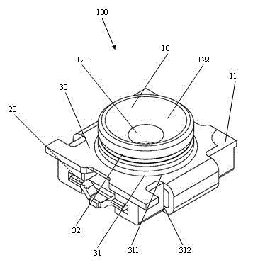
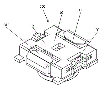
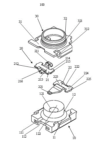
[0018] Please refer to Figure 1-4 As shown, the coaxial connector 100 of the present invention includes an insulating body 10, a conductive terminal 20 installed on the insulating body 10, and a metal shell 30 arranged outside the insulating body 10, and the insulating body 10 is injection-molded on the metal Inside the housing 30. The coaxial connector 100 can be surface soldered to an external circuit board (not shown).

[0019] Please refer to Figure 1-4 As shown, the insulating body 10 is formed with a flat base 11 and a docking portion 12 vertically extending from the base 11 to one side, and the docking portion 12 is provided with a receiving portion 121 for inserting a docking connector (not shown). . The receiving portion 121 is cylindrical. The free end of the docking part 12 is provided with a guide part 122 whose diameter is larger than that of the receiving part 121. The shape of the guiding portion 122 is bell-shaped, so that when the butting connector is i...


PUM


Abstract

The invention discloses a coaxial connector. The coaxial connector comprises an insulation body, a conductive terminal arranged on the insulation body and a metal housing arranged on the outer side of the insulation body, wherein the insulation body is arranged at the inner side of the metal housing by injection; a flat base part and a butting part integrally and perpendicularly extending to one side from the base part are arranged on the insulation body; the butting part is provided with a receiving part for insertion of a butting connector; a mounting groove communicated with the receiving part is arranged in the base part; the conductive terminal is assembled and combined onto the insulation body through the mounting groove; and the metal housing is provided with a welding part which is embedded in the base part, is far away from one side of the butting part and is exposed outwards.

Description

technical field [0001] The invention relates to a coaxial connector, in particular to the structure of the insulating body of the coaxial connector. Background technique [0002] Chinese Utility Model Patent No. CN201134587 announced on October 15, 2008 discloses a coaxial connector that can be surface-welded to an external circuit board, which includes an insulating body, a conductive terminal accommodated in the insulating body, and a set Metal shell on the outside of the insulating body. The insulating body includes an insulating seat and an insulating cover matched with the insulating seat. The conductive terminal includes a fixed terminal and a movable terminal matched with the fixed terminal. When the docking connector is not inserted, the movable terminal cooperates with the fixed terminal. After the docking connector is inserted and mated, the movable terminal Disconnect from the fixed terminal. The metal shell includes a welding part formed by bending and extendi...

Claims


Application Information

Patent Timeline
Patent Type & Authority Applications(China)
IPC IPC(8): H01R13/46H01R13/516H01R13/02H01R4/02H01R24/38
Inventor 邰军刘俊
Owner KUNSHAN JIAHUA ELECTRONICS
Why Eureka
Try Eureka