Supercharge Your Innovation With Domain-Expert AI Agents!

Field structure of an electrical machine

A technology of field structure and generator, applied in the field of field structure, can solve the problems of increasing the total weight of the rotor, wide air gap, dangerous method, etc.

Active Publication Date: 2013-02-06
SIEMENS GAMESA RENEWABLE ENERGY AS
View PDF4 Cites 4 Cited by
  • Summary
  • Abstract
  • Description
  • Claims
  • Application Information

AI Technical Summary

Problems solved by technology

This design therefore has several disadvantages, such as the need to attach a number of rather strong and thus heavy holders to the rotor surface, which increases the overall weight of the rotor
Additionally, the retainer needs to extend beyond the upper surface of the magnet to effectively hold the magnet in place, which may require a wide air gap
[0005] For the above reasons, prior art methods of mounting permanent magnets to the field of an electric motor are dangerous and difficult to perform, are problematic during repairs or involve costly machining steps

Method used


Image

  • Field structure of an electrical machine
  • Field structure of an electrical machine
  • Field structure of an electrical machine

Examples


Embodiment Construction

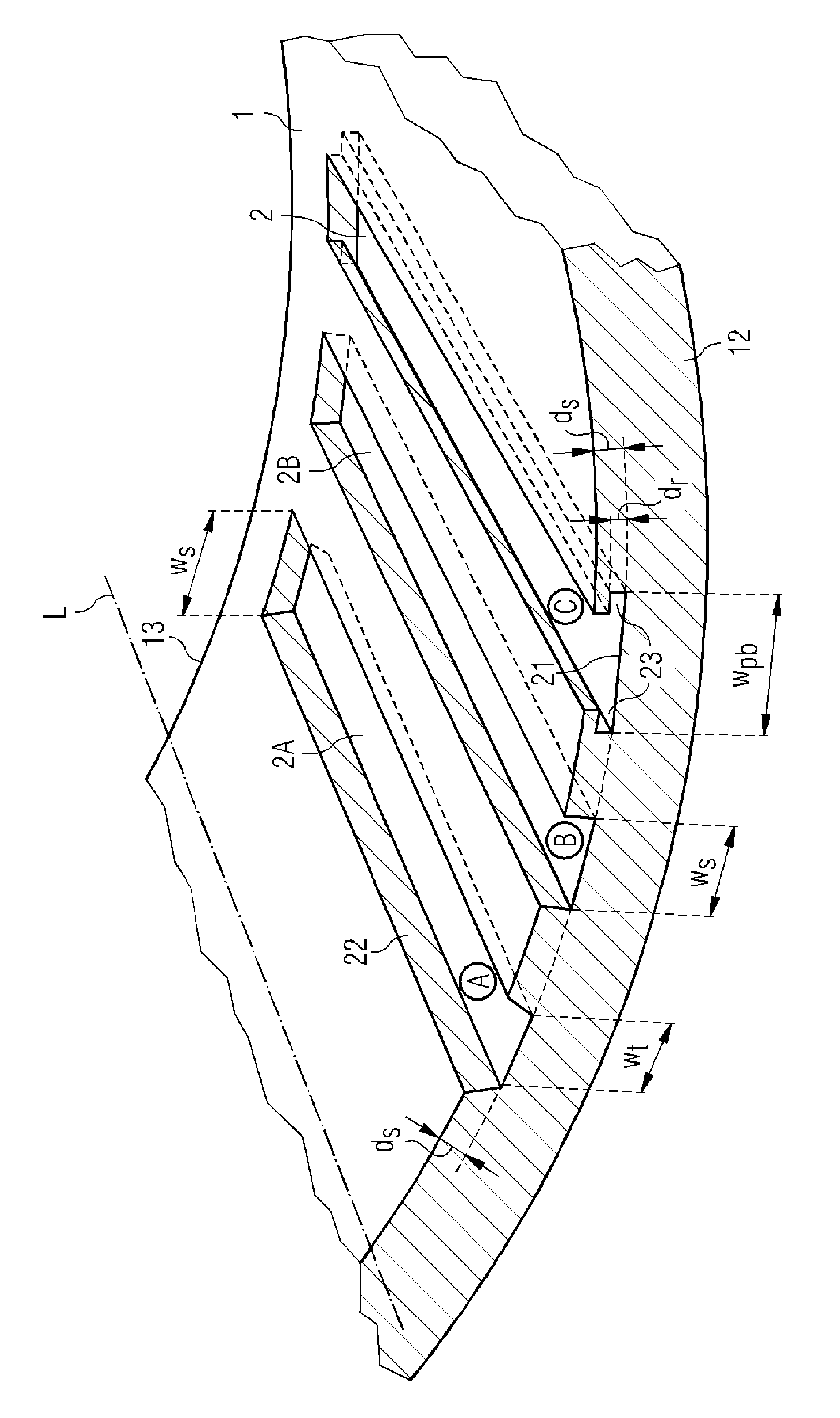
[0037] The same reference numerals refer to the same objects throughout the drawings. Objects in the drawings are not necessarily drawn to scale. In particular, the relative lengths and widths of the rotor slots or magnet assemblies may not correspond to the lengths and widths of actual embodiments of these components, they are depicted as such for clarity only.

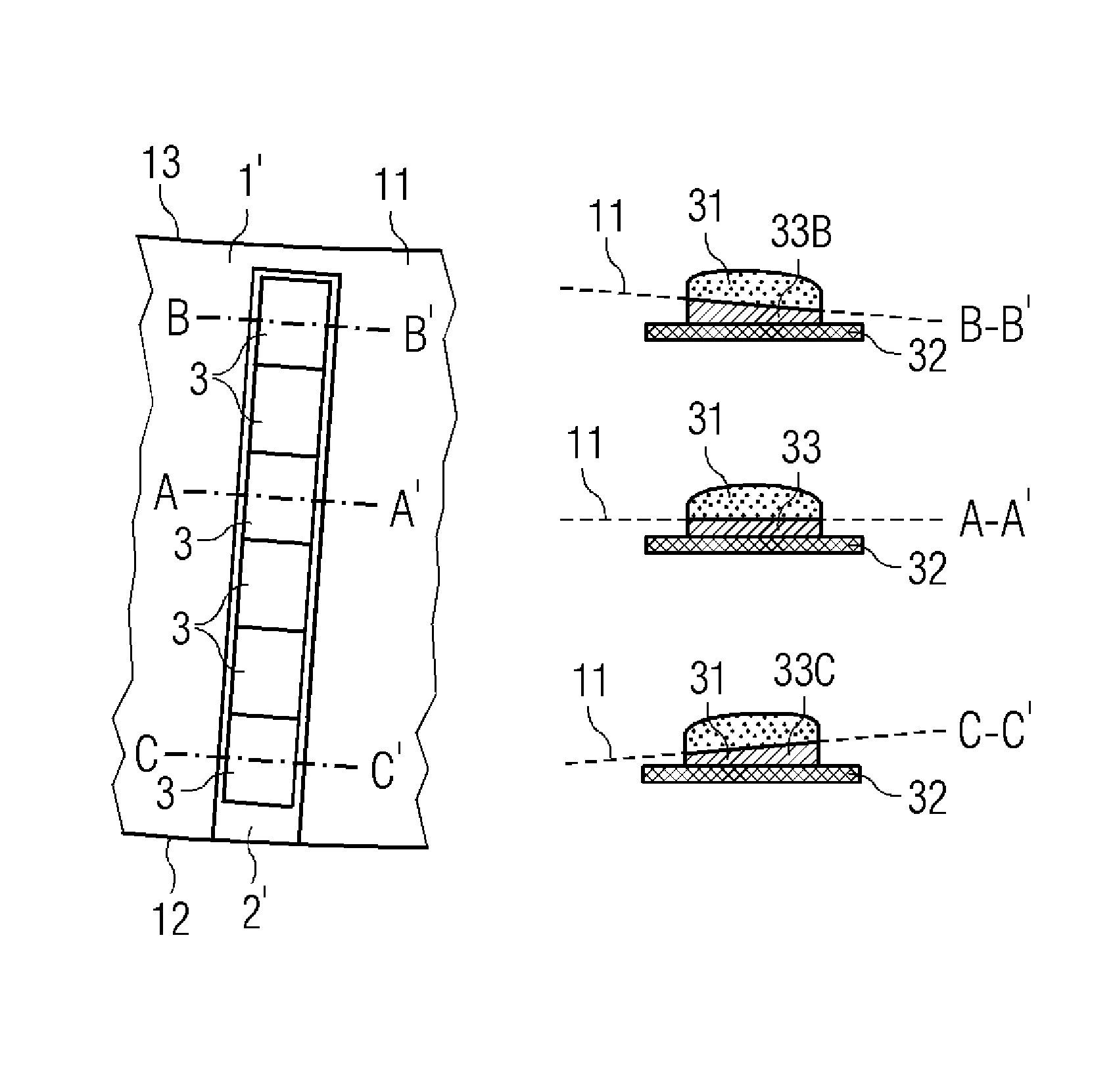
[0038] figure 1 A magnet assembly 3 according to a first embodiment of the invention is shown. Here, the magnet assembly 3 includes a base plate 32 on which an intermediate plate 33 is mounted. The pole pieces 31 are mounted on the intermediate plate 33 . Here, four such pole pieces 31 separated by small air gaps are arranged on a carrier 32 , 33 . Of course, this number is only exemplary. The intermediate plate 33 is spot welded to the base plate 32 , with the welds being located between adjacent pole pieces 31 . The magnet arrangement can be sealed in a metal or epoxy cover (not shown here) to protect against...


PUM


Abstract

The invention describes a field structure of an electrical machine, which field structure comprises a plurality of field slots, wherein a field slot extends from a first surface of the field structure into the body of the field structure, and wherein a field slot comprises a T-shaped cross-sectional area dimensioned to accommodate a magnet pole assembly comprising a corresponding cross-sectional area. The invention further describes a magnet pole assembly comprising a pole piece attached to a carrier, wherein at least part of the carrier is wider than the pole piece, and wherein the carrier (comprises a T-shaped cross-sectional area dimensioned to fit into the T-shaped field slot of such a field structure. The invention also describes an electrical machine comprising an armature structure and such a field structure, and a plurality of such magnet pole assemblies arranged in the field slots of the field structure. The invention also describes a method of forming a T-shaped field slot in a field structure of an electrical machine.

Description

technical field [0001] The invention describes a field structure of an electrical machine, a pole assembly, an electrical machine and a method of forming T-shaped field slots in the field structure. Background technique [0002] Permanent magnets are commonly used in large electric machines such as electric motors or generators. Such an electric machine consists of two basic components, a field for generating magnetic flux and an armature for generating electromotive force and carrying current across the field. The armature usually consists of conductive coils wound on the stator and the field usually consists of magnets arranged on the rotor. The rotor can surround the stator and vice versa, with the magnets and coils facing each other across a narrow air gap. The established method of loading or mounting permanent magnets onto the field (or "field structure") of an electric machine involves steps such as enclosing the individual permanent magnet poles in a housing and gl...

Claims


Application Information

Patent Timeline
Patent Type & Authority Applications(China)
IPC IPC(8): H02K1/06H02K1/27H02K1/28
CPCH02K7/1838H02K2201/06Y02E10/725H02K1/2786H02K2213/03H02K1/278Y10T29/49009Y02E10/72H02K1/2791H02K1/276
Inventor J.K.布思U.埃里克森B.N.雅各布森R.尼尔森
Owner SIEMENS GAMESA RENEWABLE ENERGY AS
Features
  • R&D
  • Intellectual Property
  • Life Sciences
  • Materials
  • Tech Scout
  • Unparalleled Data Quality
  • Higher Quality Content
  • 60% Fewer Hallucinations
Learn More