Single-phase unsymmetrical multi-level inverter with pre-charging circuit and charging method of single-phase unsymmetrical multi-level inverter

A multi-level inverter, pre-charging circuit technology, applied in systems that store electrical energy, conversion of irreversible DC power input to AC power output, electrical components, etc., to achieve high efficiency, compact structure, and reduced number of effects.

Inactive Publication Date: 2013-02-06
HARBIN EAST ALARM EQUIP DEV
View PDF0 Cites 25 Cited by
  • Summary
  • Abstract
  • Description
  • Claims
  • Application Information

AI Technical Summary

Problems solved by technology

[0005] The object of the present invention is to provide a single-phase asymmetric multilevel inverter including a pre-charging circuit and its charging method, to solve the problem of floating capacitance in the initial power-on process of the asymmetric multilevel inverter containing floating capacitance charging problem

Method used


Image

  • Single-phase unsymmetrical multi-level inverter with pre-charging circuit and charging method of single-phase unsymmetrical multi-level inverter
  • Single-phase unsymmetrical multi-level inverter with pre-charging circuit and charging method of single-phase unsymmetrical multi-level inverter
  • Single-phase unsymmetrical multi-level inverter with pre-charging circuit and charging method of single-phase unsymmetrical multi-level inverter

Examples


specific Embodiment approach 1

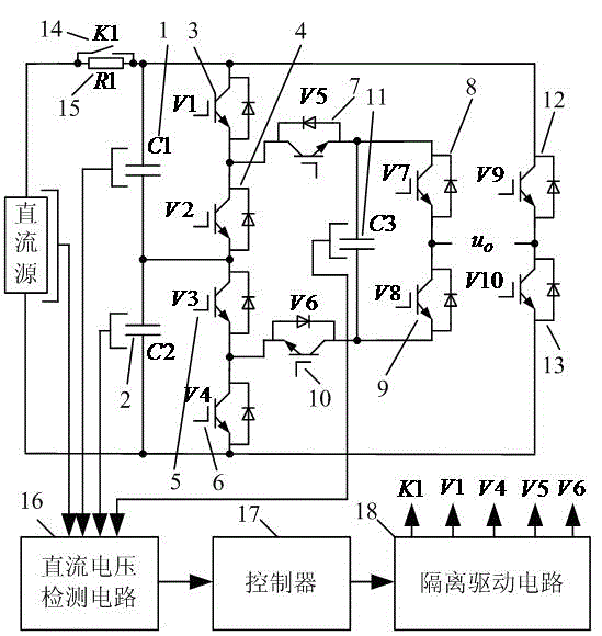
[0025] Specific implementation mode one: Combine below Figure 1 to Figure 6 This embodiment will be specifically described. figure 1 A schematic diagram of a single-phase asymmetric nine-level inverter including a pre-charging circuit, a single-phase asymmetric multi-level inverter including a pre-charging circuit, which consists of capacitors C1 (1), capacitors C2 ( 2), power switch tube V1 (3), power switch tube V2 (4), power switch tube V3 (5), power switch tube V4 (6), power switch tube V5 (7), power switch tube V7 (8) , power switch tube V8 (9), power switch tube V6 (10), capacitor C3 (11), power switch tube V9 (12), power switch tube V10 (13), switch K1 (14), charging resistor R1 (15 ), DC voltage detection circuit (16), controller (17), isolated drive circuit (18);

[0026] One end of the capacitor C1 (1) is connected to one end of the capacitor C2 (2), the power output end of V2 (4) and the power input end of V3 (5), and the other end of C2 (2) is connected to the...

specific Embodiment approach 2

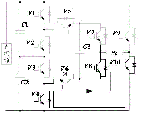
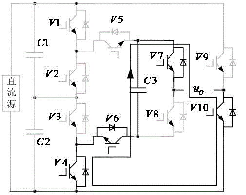
[0035] Specific implementation mode two: Combine below Figure 7 to Figure 9 This embodiment will be specifically described. The flow chart of the charging method of the single-phase asymmetric multi-level inverter including the pre-charging circuit is as follows Figure 7 As shown, its control steps are:

[0036] 1. When the power is initially turned on, the switch K1 (14) is turned off, and the voltages of the DC input power supply, capacitor C1 (1), capacitor C2 (2) and capacitor C3 (11) are respectively detected by the DC voltage detection circuit (16), and convert it into a detected low voltage signal and input it to the controller (17);

[0037] 2. In the controller (17), add the voltage of the capacitor C1 (1) and the voltage of the capacitor C2 (2), and subtract the obtained voltage sum from the DC input power supply voltage. When the voltage sum and DC When the difference between the input power supply voltages is less than the smaller difference, it means that t...


PUM


Abstract

The invention relates to a single-phase unsymmetrical multi-level inverter with a pre-charging circuit and a charging method of the single-phase unsymmetrical multi-level inverter, belonging to the field of electric energy conversion. The single-phase unsymmetrical multi-level inverter is used for converting direct current to alternating current. The single-phase unsymmetrical multi-level inverter comprises a switch, a charging resistor, ten power switch elements and three capacitors, wherein the selector switch is connected in parallel with the charging resistor and then connected in series between a direct current input power source and the direct current anode of the single-phase unsymmetrical multi-level inverter. At the initial moment of electrifying, the selector switch is cut off, the direct current input power source charges the two serial capacitors at a direct current input end through the charging resistor; after the two serial capacitors are charged, the voltage of a suspension capacitor is acquired, and the two power switch elements which are used for connecting the suspension capacitor and an anode busbar of the inverter are conducted with the two power switch elements which are used for connecting the suspension capacitor and the cathode busbar of the inverter; and when the voltage of the suspension capacitor is equal to 1 / 4 of the voltage of a direct current power source, the conducted power switch elements are cut off, and the selector switch is closed. The single-phase unsymmetrical multi-level inverter has the advantages of compact structure, low cost, easiness for implementation, high efficiency, high reliability and the like.

Description

technical field [0001] The invention relates to a single-phase asymmetrical multi-level inverter including a pre-charging circuit and a charging method thereof, which belongs to the field of electric energy conversion and is used for converting DC voltage into AC voltage. Background technique [0002] Compared with two-level DC-AC conversion technology, multi-level power conversion technology has lower voltage change rate stress and smaller voltage harmonic wave content. With the mature application of fully-controlled switching devices and the emergence of new fully-controlled devices such as IECT and IGCT, as well as the popularization of high-performance digital control technology with DSP and FPGA as the core, the research and application of multi-level inverters have been greatly improved. It has developed rapidly and has become a research hotspot in recent years. [0003] According to the topology of the main circuit, multilevel inverters can be divided into three ty...

Claims


Application Information

Patent Timeline
Patent Type & Authority Applications(China)
IPC IPC(8): H02M7/49H02J15/00
CPCH02M7/487H02M1/0095H02M7/4837
Inventor 李宣南毛飞王锡铜
Owner HARBIN EAST ALARM EQUIP DEV
Why Eureka
Try Eureka