
Testing system and testing method of multi-format video decoder

A technology for video decoders and testing methods, which is applied in the field of multi-format video decoder test systems, can solve the problems of less FPGA verification and large logic resources of multi-format video decoders, and achieve the effect of real-time viewing of decoding effects

Inactive Publication Date: 2013-02-06
FUZHOU ROCKCHIP SEMICON
View PDF9 Cites 20 Cited by
  • Summary
  • Abstract
  • Description
  • Claims
  • Application Information

AI Technical Summary

Problems solved by technology

[0004] The existing situation is that because the logic resources occupied by the multi-format video decoder are too large to be installed in ordinary FPGAs, module verification, integration verification and system verification are usually used more often, and FPGA verification is less; in addition , even for FPGA verification, it is a big problem for a large number of data input and output operations required by the test case, including what device to store, how to transfer and how fast the transfer is, etc.

Method used


Image

  • Testing system and testing method of multi-format video decoder
  • Testing system and testing method of multi-format video decoder
  • Testing system and testing method of multi-format video decoder

Examples


Embodiment Construction

[0028] In order to describe the technical content, structural features, achieved goals and effects of the present invention in detail, the following will be described in detail in conjunction with the embodiments and accompanying drawings.

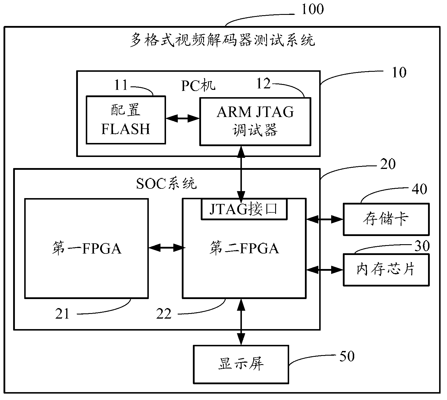
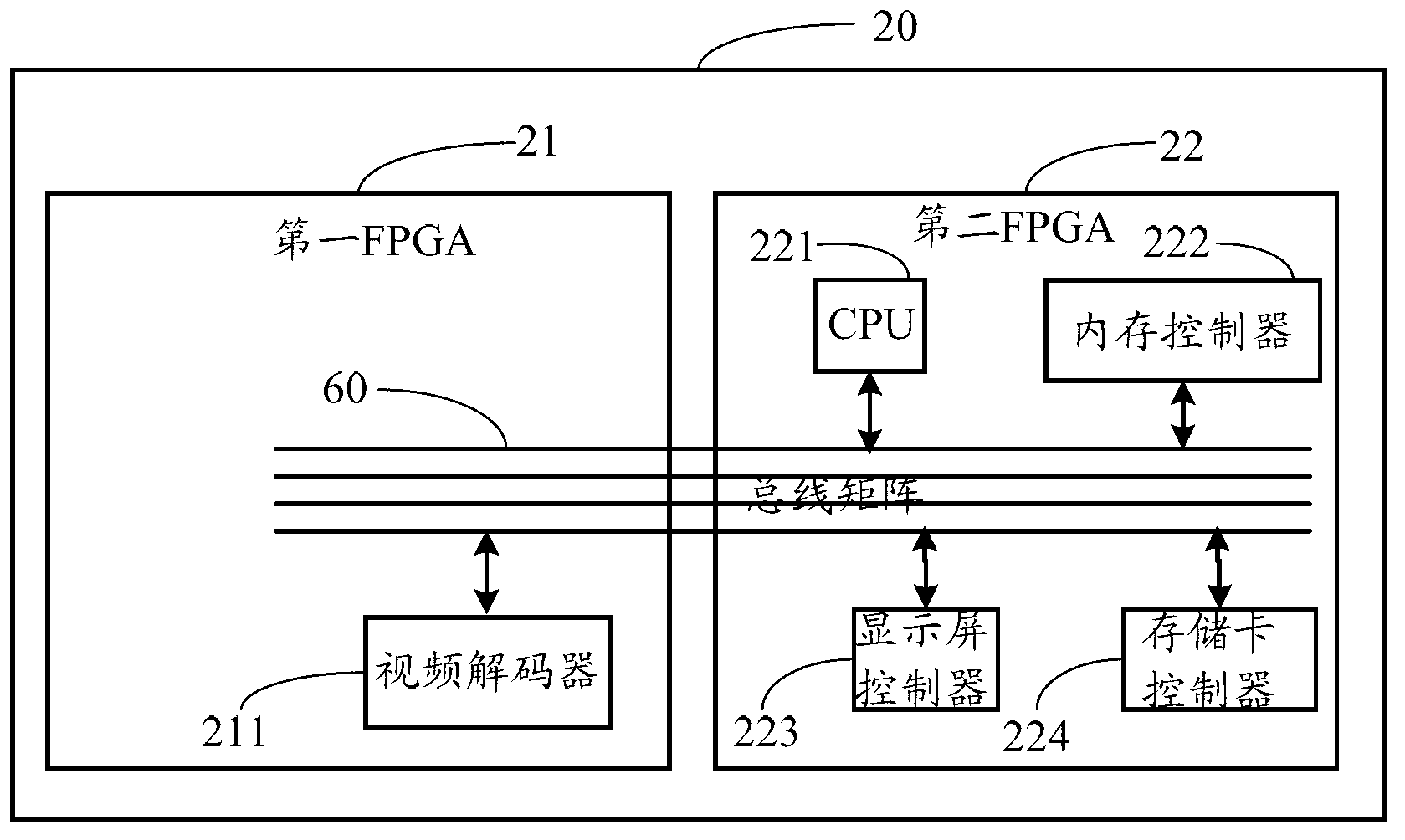
[0029] see figure 1 , is a structural block diagram of a test system for a multi-format video decoder in an embodiment of the present invention. The test system 100 of the multi-format video decoder includes a PC 10, an SOC system 20, a memory chip 30, a memory card 40, and a display screen 50, wherein the SOC system 20 includes a first FPGA 21 and a second FPGA 22, for For convenience of description, the first FPGA 21 and the second FPGA 22 are defined as dual FPGAs. Wherein, the second FPGA 22 is electrically connected to the PC 10 , the first FPGA 21 , the memory chip 30 , the memory card 40 and the display screen 50 respectively.

[0030]The PC 10 is used for compiling and debugging test programs, and the PC 10 includes an ARM JTAG d...


PUM


Abstract

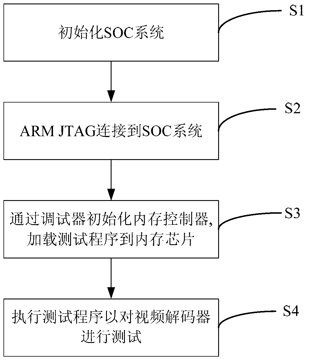
The invention discloses a testing method of a multi-format video decoder. The testing method comprises the following steps of: reading programmable data from a configuration FLASH by a PFGA (field-programmable gate array), finishing initialization of an SOC (system on chip) system; connecting a PC (personal computer) machine to a JTAG (joint test action group) interface of the SOC system through an ARM (advanced reduced instruction set computing machines) JTGA debugger connection wire; initializing an internal memory controller, loading test program to an internal memory chip from the PC machine, and carrying out a test program to test the video decoder. A testing system of the multi-format video decoder is also disclosed by the invention.

Description

technical field [0001] The invention relates to a testing system and testing method of a multi-format video decoder. Background technique [0002] In the field of SOC (System on Chip, System on Chip) design, many IP (Intellectual Property, Intellectual Property) must be fully verified before use, including module verification, integration verification, system verification and FPGA (Field Programmable Gate Array, Field-Programmable Gate Array) verification. The first three are generally software simulations, which can record the changes of various signals at different times of simulation in detail. The disadvantage is that the simulation speed is slow and the test cases of simulation are limited. However, FPGA verification can run various test cases at a speed close to the actual, which greatly speeds up the simulation speed, which is conducive to improving the coverage of test cases and speeding up the progress of testing. [0003] The multi-format video decoder is used to...

Claims


Application Information

Patent Timeline
Patent Type & Authority Applications(China)
IPC IPC(8): H04N17/00
Inventor 陈祖尚
Owner FUZHOU ROCKCHIP SEMICON
Learn More