Section-variable hollow component forming device and method

A hollow component and variable cross-section technology, which is applied in the field of processing and forming devices for metal hollow components and forming devices for variable cross-section hollow components, can solve the problems of poor deformation uniformity and difficulty in feeding materials in the axial direction, so as to achieve easy feeding and avoid partial Effect of excessive thinning and uniformity improvement

Inactive Publication Date: 2015-05-20
哈尔滨松花江汽车座椅有限责任公司
View PDF6 Cites 0 Cited by
  • Summary
  • Abstract
  • Description
  • Claims
  • Application Information

AI Technical Summary

Problems solved by technology

[0006] In order to solve the problems of difficult axial feeding and poor deformation uniformity when forming hollow members with large differences in cross-sectional dimensions in traditional pipe hydroforming, the present invention further provides an internal pressure forming device and method for hollow members with variable cross-sections

Method used


Image

  • Section-variable hollow component forming device and method
  • Section-variable hollow component forming device and method
  • Section-variable hollow component forming device and method

Examples


specific Embodiment approach 1

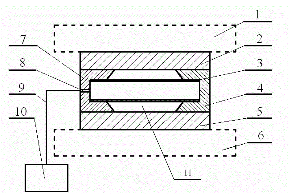
[0019] Specific implementation mode one: as Figure 1-4 As shown, the variable cross-section hollow member internal pressure forming device includes an upper die base 2, a left punch 7, a right punch 4, a lower die base 5, a liquid channel 9 and a supercharger 10, a left punch 7, a right punch The head 4 is located between the upper die base 2 and the lower die base 5, and the upper die base 2, the left punch 7, the right punch 4 and the lower die base 5 form a closed cavity 11, and the left punch 7 or There is a punch liquid injection hole 8 on the right punch 4, the supercharger 10 communicates with the punch liquid injection hole 8 through the liquid channel 9, and the punch liquid injection hole 8 is used to place the left punch 7 and the right punch. Liquid medium is injected into the tube blank 3 on the punch.

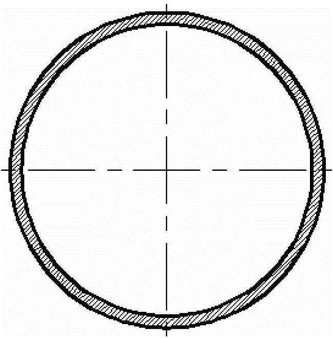
[0020] The cross section of the diameter reducing portion of the closed cavity 11 may be circular, rhombus, square or rectangular.

specific Embodiment approach 2

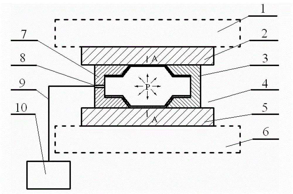
[0021] Specific implementation mode two: as Figure 1-4 As shown, this embodiment is a method for internal pressure forming of a hollow member with a variable cross-section using the above-mentioned forming device. The method is realized according to the following steps: Step 1. Fix the lower mold base 5 on the lower workbench 6 of the press; step 2. Move the right punch 4 to the right end of the lower mold base 5, and place one end of the tube blank 3 in the mold cavity of the right punch 4; step 3, move the left punch 7 to the lower mold base 5 and place the other end of the tube blank 3 in the mold cavity of the left punch 7; step 4, move down the upper worktable 1 of the press, so that the upper die base 2 is aligned with the left punch 7 and the right punch 4 Form a closed cavity 11 with the lower mold base 5; step five, pressurize the tube material 3 through the supercharger 10; step six, the left punch 7 and the right punch 4 simultaneously push the tube material 3 to m...


PUM


Abstract

The invention provides a section-variable hollow component forming device and a section-variable hollow component forming method, belongs to the technical field of hydraulic formation, and solves the problems that when a hollow component with a large hydraulic formation section size difference of a traditional tubular product is formed, axial feeding is difficult, the deformation uniformity is poor and the like. A closed cavity is formed by an upper die base, a left puncher pin, a right puncher pin and a lower die base; a puncher pin liquid injection hole is formed on the left puncher pin or the right puncher pin; a pressurizing device is communicated with the puncher pin liquid injection hole through a liquid channel; and the puncher pin liquid injection hole is used for injecting a liquid medium into a pipe blank. A pipe blank is placed into a die cavity and the puncher pins at the two ends are used for fixing the pipe blank; the upper die base is moved downwards to form a sealed hollow cavity with the lower die base; a force transfer medium is injected into the tubular product from the puncher pin injection hole at one side to pressurize; and the formation of a diameter-changing tube piece is realized under the matching effect of moving the left and right puncher pins to the inner side. After the formation, pressure in the die cavity can be removed after the formation, the upper die base is removed to separate the left and right puncher pins, and the formed piece is taken out. The section-variable hollow component forming device and the section-variable hollow component forming method are suitable for forming the hollow component with the great change of the section size and the circular-section or non-circular-section diameter-changing part.

Description

technical field [0001] The invention relates to a forming device and method for a metal hollow member, in particular to a forming device and method for a variable-section hollow member, and belongs to the technical field of hydroforming. Background technique [0002] With the increasing demand for production and the gradual acceleration of the industrialization process, unprecedented opportunities and challenges have been provided for the processing and manufacturing of parts, especially in the advanced manufacturing fields represented by aerospace and automobiles. Comprehensive performance and other aspects have put forward higher requirements. [0003] Reducing weight to save raw materials and energy consumption is a long-term pursuit of people, and light weight is one of the ideal ways. There are two main ways to achieve this: one is the material way, using lightweight materials such as aluminum alloys, magnesium alloys, titanium alloys and composite materials; It can n...

Claims


Application Information

Patent Timeline
Patent Type & Authority Patents(China)
IPC IPC(8): B21D26/033
Inventor 李峰徐明达石文勇石玮边楠
Owner 哈尔滨松花江汽车座椅有限责任公司
Why Eureka
Try Eureka