
Method for cutting tempered glass

A technology for strengthening glass and cutting methods, applied in glass cutting devices, glass production, glass manufacturing equipment, etc., can solve the problems of easy breakage of glass, low production efficiency, and reduced glass strength, so as to reduce the breakage rate, improve production efficiency, The effect of improving the compressive strength

Active Publication Date: 2013-02-13
WGTECH JIANGXI
View PDF7 Cites 48 Cited by
  • Summary
  • Abstract
  • Description
  • Claims
  • Application Information

AI Technical Summary

Problems solved by technology

Due to the tensile stress inside the strengthened glass, the edge of the strengthened glass is jagged after physical cutting, the glass strength is reduced, and the glass is easy to break. At the same time, because the cut glass is easy to break, the operator dare not use force to operate quickly, resulting in low production efficiency.

Method used


Image

  • Method for cutting tempered glass
  • Method for cutting tempered glass
  • Method for cutting tempered glass

Examples


Embodiment 1

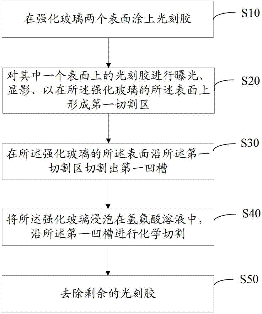
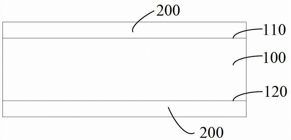
[0055] Coat 50 μm photoresist on both surfaces of the strengthened glass.

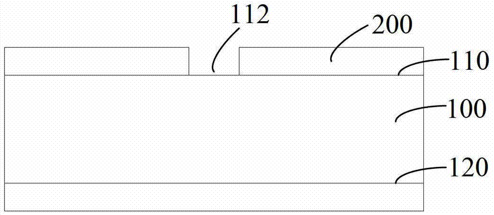
[0056] Exposing and developing the photoresist on one of the surfaces to form a first cutting area on the surface of the strengthened glass.

[0057] A V-shaped groove with a depth of 0.03 mm is cut along the first cutting zone on the surface of the strengthened glass.

[0058] The strengthened glass is soaked in a hydrofluoric acid solution with a concentration of 40% by mass, and chemically cut along the V-shaped groove.

[0059] Use the stripper Ecostrip to remove the remaining photoresist.

[0060] Wherein, the thickness of the strengthened glass is 0.77mm, the immersion temperature is 33°C, and the immersion time is 900s.

Embodiment 2

[0062] Coat 100 μm photoresist on both surfaces of the strengthened glass.

[0063] Exposing and developing the photoresist on one of the surfaces to form a first cutting area on the surface of the strengthened glass.

[0064] A square groove with a depth of 0.08 mm is cut along the first cutting zone on the surface of the strengthened glass.

[0065] The strengthened glass is soaked in a hydrofluoric acid solution with a concentration of 30% by mass, and chemically cut along the square groove.

[0066] Use the stripper Ecostrip to remove the remaining photoresist.

[0067] Among them, the thickness of the strengthened glass is 0.77mm, the soaking temperature is 33°C, and the soaking time is 3600s.

Embodiment 3

[0069] Coat 50 μm photoresist on both surfaces of the strengthened glass.

[0070] The photoresist on both surfaces is exposed, developed to form two cutting regions on the surface of the strengthened glass.

[0071] V-shaped grooves with a depth of 0.08 mm are cut along the two cutting regions on the surface of the strengthened glass.

[0072] The strengthened glass is soaked in a hydrofluoric acid solution with a concentration of 30% by mass, and chemically cut along the V-shaped groove.

[0073] Use the stripper Ecostrip to remove the remaining photoresist.

[0074] Wherein, the thickness of the strengthened glass is 0.77mm, the immersion temperature is 33°C, and the immersion time is 1200s.


PUM

PropertyMeasurementUnit
Thicknessaaaaaaaaaa

Abstract

The invention provides a method for cutting tempered glass. The method comprises the following steps of: coating photoresist on two surfaces of the tempered glass, and performing exposure and developing on the photoresist on one surface, so that a first cutting area is formed on the surface of the tempered glass; cutting a first groove on the surface of the tempered glass along the first cutting area; soaking the tempered glass in a hydrofluoric acid solution, and performing chemical cutting along the first groove; and removing the residual photoresist. According to the method, the tempered glass is cut by using the hydrofluoric acid solution, and the edge of the tempered glass is smoothed, so that the compressive strength on the edge of the tempered glass is improved, the breakage rate of the cut tempered glass is reduced, and the production efficiency is improved.

Description

technical field [0001] The invention relates to a cutting process of glass, in particular to a cutting method of strengthened glass. Background technique [0002] After the glass is strengthened, uniform compressive stress is formed on the surface of the glass, and tensile stress is formed inside, so that the bending and impact strength of the glass can be improved. Due to the tensile stress inside the strengthened glass, the edge of the strengthened glass is jagged after physical cutting, the glass strength is reduced, and the glass is easy to break. At the same time, because the cut glass is easy to break, the operator dare not use force to operate quickly, resulting in low production efficiency. . Contents of the invention [0003] Based on this, it is necessary to provide a cutting method of strengthened glass with high compressive strength after cutting and high production efficiency. [0004] A method for cutting tempered glass, comprising the steps of: [0005] C...

Claims


Application Information

Patent Timeline
IPC IPC(8): C03B33/02
CPCY02P40/57
Inventor 杨会良况俊文
Owner WGTECH JIANGXI
Learn More