
Complex-wave type harmonic drive speed reducer

A technology of harmonic drive and reducer, applied in the direction of transmission, transmission parts, gear transmission, etc., to achieve the effect of large transmission ratio, compact structure and small outline size

Inactive Publication Date: 2013-02-13
陕西渭河工模具总厂
View PDF6 Cites 13 Cited by
  • Summary
  • Abstract
  • Description
  • Claims
  • Application Information

AI Technical Summary

Problems solved by technology

Therefore, for users who require linear harmonic deceleration and require a large deceleration ratio, this has disadvantages in use

Method used


Image

  • Complex-wave type harmonic drive speed reducer
  • Complex-wave type harmonic drive speed reducer
  • Complex-wave type harmonic drive speed reducer

Examples


Embodiment Construction

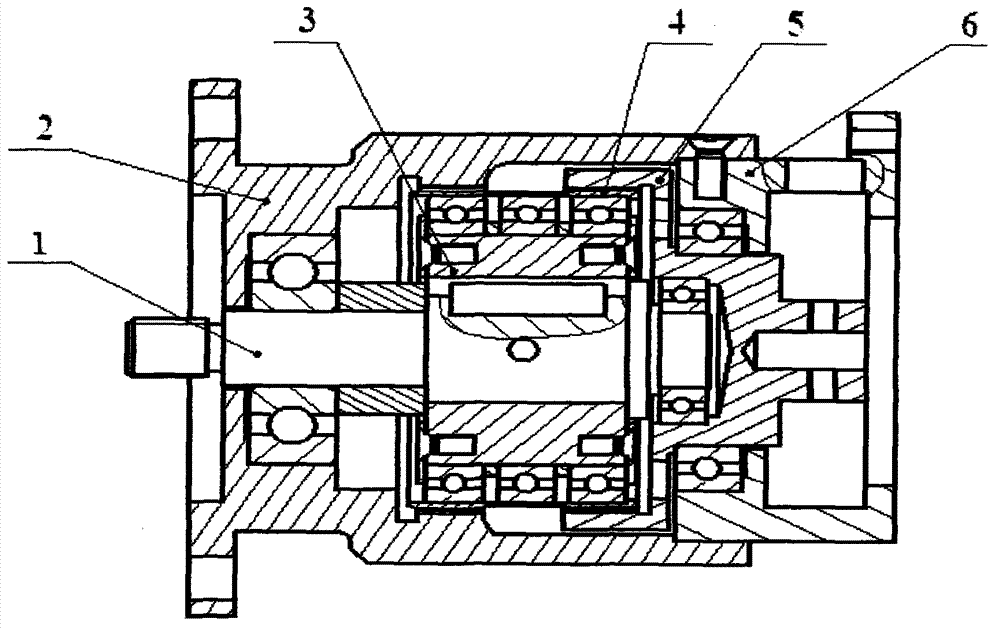
[0012] Embodiments of the present invention will be further described below in conjunction with the accompanying drawings.

[0013] Such as figure 1 As shown, the compound wave harmonic transmission reducer of the present invention includes an input shaft 1, a fixed rigid wheel (ie, a housing) 2, a wave generator 3, a double flexible wheel 4, an output rigid wheel 5, and an end cover 6. Among them, the wave generator 3 and the input shaft 1 are tightly connected by keys and cylindrical pins, and the output steel wheel 5 is integrated with the output part, and the torque is transmitted in the form of a shaft, and the deceleration is realized. The motor drives the input shaft 1 to rotate at a high speed, and the input shaft 1 drives the wave generator 3 to rotate, causing controllable deformation to the flex spline 4. The external gear at one end of the flex spline 4 meshes with the internal gear of the fixed rigid spline 2, resulting in a tooth-staggered movement. The first-or...


PUM


Abstract

The invention provides a complex-wave type harmonic drive speed reducer, which comprises a wave generator, a flexible gear, a fixed rigid gear and an output rigid gear, wherein the wave generator is provided with cams, a first flexible bearing and a second flexible bearing; the flexible gear is provided with a first external gear and a second external gear which are respectively arranged at two ends of the flexible gear; a first external gear of the flexible gear is meshed with the fixed rigid gear through the cam via the first flexible bearing, and the second external gear of the flexible gear is meshed with the output rigid gear through the cam via the second flexible bearing. The complex-wave type harmonic drive speed reducer has the advantages of realization of two-stage harmonic-drive speed reduction in the form of complex waves, compact structure, small volume, large transmission ratio, high transmission precision and wide range of application.

Description

technical field [0001] The invention belongs to the field of mechanical transmission, and in particular relates to a harmonic drive reducer. Background technique [0002] In the prior art, the harmonic transmission reducer plays an important role in the subsystems of attitude adjustment and automatic control during the flight movement of the flight carrier. Due to its small size, light weight, and large output torque, it is The market demand is increasing year by year, and it is widely used in various fields of various industries, especially in some special fields, which require a large reduction ratio. [0003] The single-stage linear harmonic reducer widely used at present, due to the influence of the torque, the selected harmonic model (the model is usually distinguished by the inner diameter of the flexible spline), the gear module and the processing tool, the flexspline and rigid spline The module of the wheel should not be too small, that is, the reduction ratio of th...

Claims


Application Information

Patent Timeline
IPC IPC(8): F16H1/32F16H57/08
Inventor 李剑敏胡彩侠刘军吕平华
Owner 陕西渭河工模具总厂
Learn More