
Pilot-operated double-spool split-range adjusting valve

A technology of pilot valve core and double valve core is applied in the field of fluid control regulating valve, which can solve the problems of large dead zone and inability to realize precise adjustment of flow with small opening, and achieve the effect of saving the number of use, compact structure and improving economic benefits.

Inactive Publication Date: 2013-02-13
WUXI SMART AUTO CONTROL ENG CO LTD
View PDF9 Cites 7 Cited by
  • Summary
  • Abstract
  • Description
  • Claims
  • Application Information

AI Technical Summary

Problems solved by technology

According to the above working conditions, the existing control valve cannot meet its actual requirements, because the normal adjustment opening of the existing control valve is between 30% and 70%, the adjustable ratio is 30:1, and the dead zone is large; and this The diameter of the pipeline is DN300. In the past, the pressure-reducing sleeve valve of DN300 was installed. Due to factors such as pipeline vibration and scouring, it will not be able to achieve the precise adjustment of the small opening flow rate during the start-up phase.
In addition, the leakage of the existing valves has far exceeded the regulated flow during the start-up stage required by the working conditions; at the same time, the existing pilot valves only have the function of small opening pressure relief and large opening adjustment, which is different from the start-up required by this working condition. Stage small opening adjustment to stabilize the system pressure, large opening adjustment, the technical requirements for large flow backflow when the system fails do not meet

Method used


Image

  • Pilot-operated double-spool split-range adjusting valve
  • Pilot-operated double-spool split-range adjusting valve
  • Pilot-operated double-spool split-range adjusting valve

Examples


Embodiment Construction

[0019] The present invention will be further described below in conjunction with specific drawings.

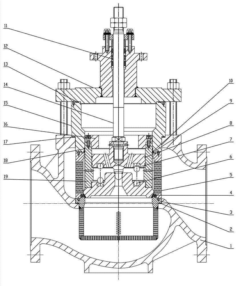
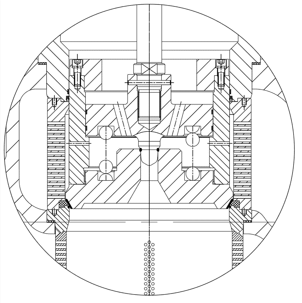
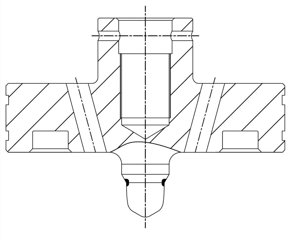
[0020] Such as figure 1 , 2 Shown: Pilot-operated double-spool split-range regulating valve consists of valve body 1, graphite composite gasket 2, valve seat 3, PTFE valve seat 4, noise reduction sleeve 5, compression spring 6, pilot spool 7, first four Fluorine guide belt 8, balance seal ring 9, energizer spring 10, packing assembly 11, upper cover 12, graphite composite gasket 13, valve stem 14, balance ring seat 15, thrust ring 16, graphite composite gasket 17, the first Parts such as PTFE guide band 18, main valve core 19 are formed.

[0021] The valve seat 3 is assembled on the inner bottom of the valve body 1, and a graphite composite gasket 2 is placed between the valve body 1, and a tetrafluoro valve seat 4 and a noise reduction sleeve 5 are assembled on the valve seat 3. After the valve stem 14 and the pilot spool 7 are connected together with pins, they are assemb...


PUM


Abstract

The invention relates to a pilot-operated double-spool split-range adjusting valve which is characterized in that a valve base is arranged in a valve body, a Teflon valve base is arranged on the valve base, a main spool is assembled on the Teflon valve base to form flexible sealing, a valve rod is integrally connected with a pilot-operated spool, and the valve rod and a compression spring are assembled in an inner cavity of the main spool. A first Teflon guide tape is arranged in a trough of the pilot-operated spool, a thrust ring is used for being connected with the main spool, and the sealing surface of the pilot-operated spool is attached to the sealing surface in the inner cavity of the main spool. A noise reduction sleeve and a balancing ring base are sequentially arranged on the valve base. A stuffing assembly is assembled in an upper cover stuffing box, and an upper cover is fixed on the valve body. By adopting the pilot-operated double-spool split-range adjusting valve, a bypass parallel-connection valve is not used for flow adjusting, and accordingly the use quantity of the valves is saved. The pilot-operated spool can meet requirement of equal percentage accurate adjusting under small opening, and the main spool can meet requirement of equal percentage accurate adjusting under large opening and achieve the function of media large flow backflow cutting in the pipeline system failure state. Flow of the pilot-operated double-spool split-range adjusting valve can be adjusted accurately and the pilot-operated double-spool split-range adjusting valve can save pipe distribution space and reduce use cost of clients.

Description

technical field [0001] The invention relates to a pilot-operated, split-range regulating valve with double spool adjustment. The valve has equal-percentage precise adjustment for small openings within the stroke range and equal-percentages for large openings. The utility model can realize the function of cutting off the backflow of the medium in the pipeline with a large flow rate, and belongs to the technical field of fluid control regulating valves. Background technique [0002] The medium in the pipeline used by this valve is nitrogen, the temperature is 40°C, the pre-valve pressure is 2.8MPaA during normal operation, the post-valve pressure is 0.54 MPaA, and the adjusted pressure difference is 2.26MPa. When the valve is working normally, the flow rate needs to meet the 400NM during the start-up phase 3 / H continuously adjustable, 30000 NM for smooth operation 3 / H is continuously adjustable; when the pipeline system fails, the valve needs to meet the maximum return flo...

Claims


Application Information

Patent Timeline
Patent Type & Authority Applications(China)
IPC IPC(8): F16K17/20F16K47/02
Inventor 陈彦盛子烨王汪洋张程
Owner WUXI SMART AUTO CONTROL ENG CO LTD
Learn More