

Three-phase-to-five-phase double-stage matrix converter based on Z source
A technology of matrix converter and matrix converter, which is applied in the direction of conversion equipment for intermediate conversion to DC, output power conversion device, conversion equipment without intermediate conversion to AC, etc., which can solve the problem of large volume, power grid harmonics Pollution, limited service life of inverters, etc.
- Summary
- Abstract
- Description
- Claims
- Application Information
AI Technical Summary
Problems solved by technology
Method used
Image

Examples
specific Embodiment approach 1
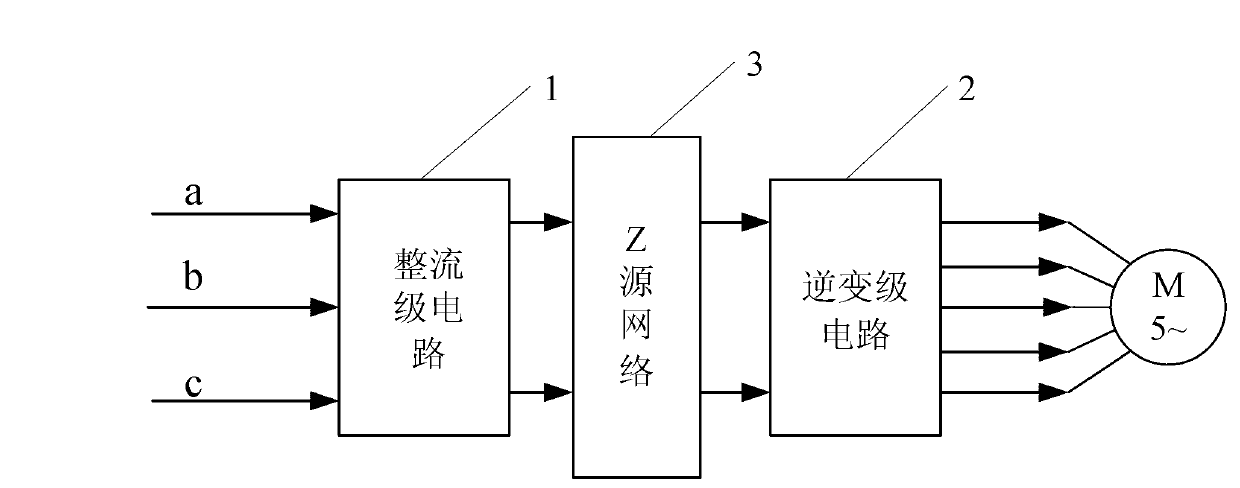
[0017] Specific implementation mode one: combine figure 2 with image 3 Describe this embodiment, the three-phase-five-phase two-stage matrix converter based on Z source described in this embodiment, it comprises bipolar matrix converter, and it also comprises Z source network 3,
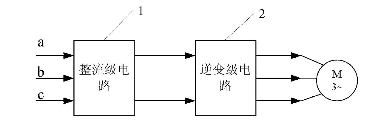
[0018] The bipolar matrix converter is composed of a rectification stage circuit 1 and an inverter stage circuit 2; a Z source network 3 is connected in series between the rectification stage circuit 1 and the inverter stage circuit 2.
specific Embodiment approach 2
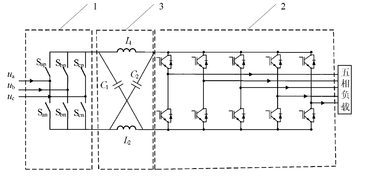
[0019] Embodiment 2: The difference between this embodiment and the three-phase-five-phase two-stage matrix converter based on Z source described in Embodiment 1 is that the rectification stage circuit 1 is composed of 6 bidirectional switches Sap, San , Sbp, Sbn, Scp and Scn are composed of a three-phase full-bridge rectifier circuit.
specific Embodiment approach 3
[0020] Specific implementation mode three: combination Figure 4 with Figure 7 This embodiment is described. The difference between this embodiment and the Z-source-based three-phase-five-phase two-stage matrix converter described in the second embodiment is that the bidirectional switches are composed of two IGBTs and two power diodes. , the two IGBTs are connected in a common-emitter type, and each IGBT is connected in parallel with a power diode, wherein the anode of the power diode is connected to the emitter of the IGBT, and the cathode of the diode is connected to the collector of the IGBT.
[0021] Each of the bidirectional switches has bidirectional turn-on and bidirectional turn-off capabilities. However, there is no power electronic switching device that can directly realize the above functions in the market. Therefore, in the research and development of the bipolar matrix converter, it is necessary to use discrete switching devices to form a bidirectional switch. ...
PUM
 Abstract
Description
Claims
Application Information