
Circuit board for frequency generator and manufacturing method thereof

A technology for making frequency generators and circuit boards, which is applied in the direction of multilayer circuit manufacturing and printed circuit components, etc., can solve the problems of increased space occupied by circuit boards, increased equipment volume of circuit boards, increased costs, etc., to achieve circuit The effect of simple board structure, short signal transmission distance and small space occupation

Inactive Publication Date: 2013-02-13
SHANGHAI RADIO EQUIP RES INST
View PDF3 Cites 5 Cited by
  • Summary
  • Abstract
  • Description
  • Claims
  • Application Information

AI Technical Summary

Problems solved by technology

For some circuits that contain both high-frequency circuits and low-frequency circuits, such as frequency generators, in order to reduce the interference of high-frequency signals on low-frequency signals, the circuit board design of the prior art usually combines high-frequency circuits with low-frequency circuits. Separate the circuit layout as much as possible, and even distribute the high-frequency circuit and the low-frequency circuit on two circuit boards. Such a circuit board design increases the space occupied by the circuit board and also increases the equipment installed on the circuit board. volume, while increasing the cost
And because the dielectric constant of ordinary epoxy boards is not suitable for the layout of high-frequency circuit signal lines, the layout of high-frequency circuit signal lines on epoxy boards requires a very large line width, and a special manufacturing process is used, which also makes the circuit board Occupies more space and costs more

Method used


Image

  • Circuit board for frequency generator and manufacturing method thereof
  • Circuit board for frequency generator and manufacturing method thereof

Examples


Embodiment Construction

[0022] The present invention will be further elaborated below by describing a preferred specific embodiment in detail in conjunction with the accompanying drawings.

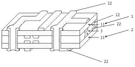
[0023] See attached figure 1 As shown, a circuit board for a frequency generator of the present invention includes: a low-frequency layer 1, a high-frequency layer 2, and an intermediate dielectric layer 3 arranged between the low-frequency layer 1 and the high-frequency layer 2; the low-frequency layer 1, The intermediate dielectric layer 3 and the high-frequency layer 2 are sequentially stacked and compounded into a whole; the low-frequency layer 1 includes a low-frequency substrate 11 and two layers of conductive pattern layers 12 respectively compounded on both sides of the low-frequency substrate 11; the high-frequency layer 2 includes high-frequency The high-frequency substrate 2 and two layers of conductive pattern layers 22 respectively compounded on both sides of the high-frequency substrate 21.

[0024...


PUM

PropertyMeasurementUnit
Thicknessaaaaaaaaaa
Thicknessaaaaaaaaaa

Abstract

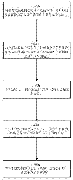
The invention discloses a circuit board for a frequency generator. The circuit board comprises a low-frequency layer, a middle medium layer and a high-frequency layer which are superimposed and composited into a whole body in sequence, wherein the low-frequency layer comprises a low-frequency substrate and two conductive pattern layers; the conductive pattern layers are respectively composited on the two side surfaces of the low-frequency substrate; the high-frequency layer comprises a high-frequency substrate and two conductive pattern layers; the conductive pattern layers are respectively composited on the two side surfaces of the high-frequency substrate. The invention discloses a manufacturing method of the circuit board for the frequency generator. The manufacturing method comprises the following steps of: compositing all the conductive pattern layers formed by partial low-frequency circuit signal lines on the two side surfaces of the low-frequency substrate to manufacture into the low-frequency layer; compositing all the conductive pattern layers formed by high-frequency circuit signal lines and partial low-frequency circuit signal lines on the two side surfaces of the high-frequency substrate to manufacture into the high-frequency layer; and superimposing the low-frequency layer, the middle medium layer and the high-frequency layer in sequence, pressing and forming. The circuit board disclosed by the invention has the advantages that the high-frequency circuit and the low-frequency circuit are integrated on the circuit board and are not interfered, the structure is simple and the occupied space is small.

Description

technical field [0001] The invention relates to a circuit board, in particular to a circuit board used for a frequency generator and a manufacturing method thereof. Background technique [0002] The transmission frequency of high-frequency signals on the circuit is usually several hundred megahertz (MHZ) to several gigahertz (GHZ), while the low-frequency signal is usually only a few kilohertz (KHZ) to several megahertz (MHZ). When the high-frequency signal line and the low-frequency signal line are close to each other on the circuit board, the high-frequency signal will strongly interfere with the low-frequency signal due to electromagnetic coupling. For some circuits that contain both high-frequency circuits and low-frequency circuits, such as frequency generators, in order to reduce the interference of high-frequency signals on low-frequency signals, the circuit board design of the prior art usually combines high-frequency circuits with low-frequency circuits. Separate t...

Claims


Application Information

Patent Timeline
IPC IPC(8): H05K1/02H05K3/46
Inventor 王磊磊朱思悦张振强
Owner SHANGHAI RADIO EQUIP RES INST
Learn More