
In-wheel motor driving device

A hub motor and driving device technology, which is applied in the direction of electromechanical devices, electrical devices, power devices, etc., can solve the problem of increased load under the spring, and achieve the effects of reducing pulling resistance, high versatility, and improving operability

Inactive Publication Date: 2013-02-13
NTN CORP
View PDF10 Cites 13 Cited by
  • Summary
  • Abstract
  • Description
  • Claims
  • Application Information

AI Technical Summary

Problems solved by technology

The increase in the size of the knuckle shape and the restrictions on the suspension configuration have caused the problem of an increase in the unsprung load, and there is a problem that the steering pin (king pin) axis deviates to the inner side of the vehicle width direction relative to the tire installation surface, so there is a problem when there is a turning wheel. pull resistance problem

Method used


Image

  • In-wheel motor driving device
  • In-wheel motor driving device
  • In-wheel motor driving device

Examples


Embodiment Construction

[0053] Hereinafter, embodiments of the present invention will be described based on the drawings.

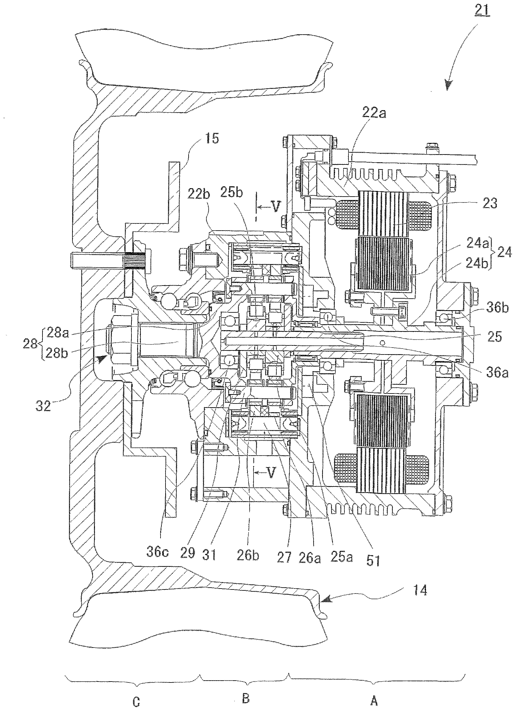
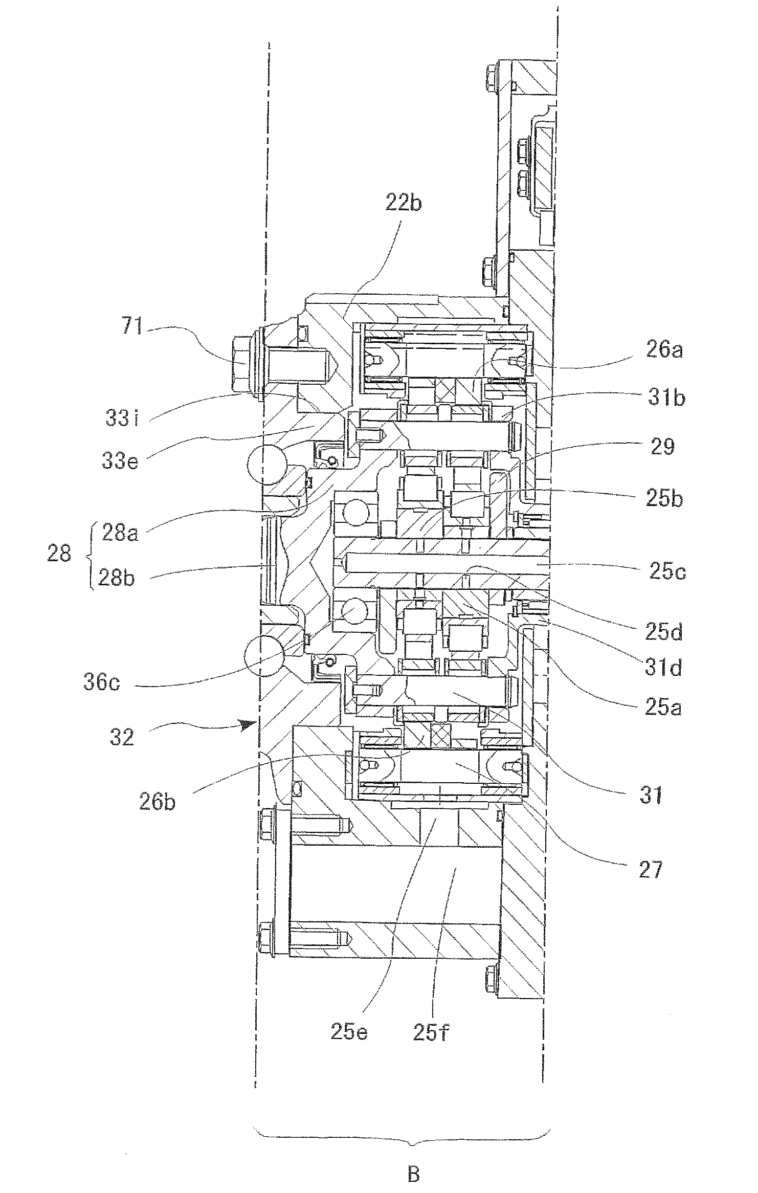
[0054] First, if figure 1 As shown, the in-wheel motor driving device 21 includes: a motor unit A that generates driving force, a deceleration unit B that decelerates the rotation of the motor unit A and outputs it, and a wheel hub bearing unit C that transmits the output from the deceleration unit B to the drive wheel 14. . Such as Figure 9 As shown, it is installed in the wheel housing 12a of the chassis 12.

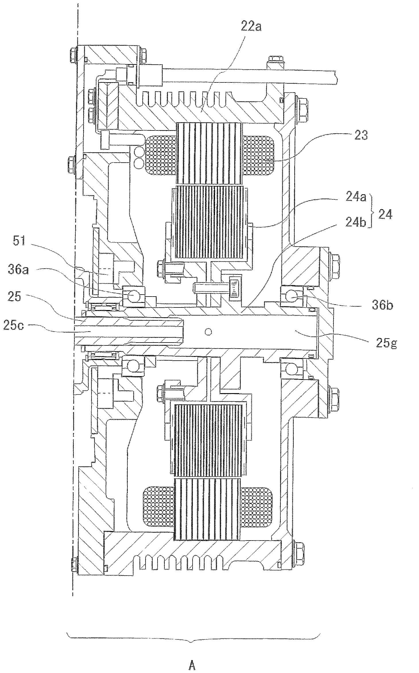
[0055] Such as figure 2As shown, the motor part A is a radial gap motor, and includes a stator 23 fixed to a casing 22a, a rotor 24 disposed at a position opposite to the inner side of the stator 23 with a gap in the radial direction, and fixedly connected to the inner side of the rotor 24 and connected to the inner side of the rotor 24. The rotor 24 is a motor-side rotating member 25 that integrally rotates. The rotor 24 has a flange-shaped rotor 24a and a cylin...


PUM


Abstract

Provided is an in-wheel motor driving device which is provided with a versatile suspension installation part, and which is light and reduces drag resistance during steering. The in-wheel motor driving device comprises: a motor unit (A) which rotates and drives a motor-side rotary member; a deceleration unit (B) which decelerates the rotation of the motor-side rotary member and transmits said rotation to a wheel-side rotary member; and a wheel hub which is fixedly linked to the wheel-side rotary member, and the motor unit (A), the deceleration unit (B), and the wheel hub are arranged in series from the inboard side to the outboard side of a vehicle, wherein a suspension installation bracket (60) is fixed to the outer surface of a housing (22b) of the deceleration unit (B), and an arm of a suspension (12b) is installed by way of the suspension installation bracket (60).

Description

technical field [0001] The present invention relates to an in-wheel motor drive device in which an electric motor constituting a drive mechanism is assembled in a wheel, particularly a suspension-mounted structure. Background technique [0002] A conventional in-wheel motor drive device 101 is described in, for example, Japanese Patent Application Laid-Open No. 2009-219271 (Patent Document 1). [0003] Such as Figure 23 As shown, the in-wheel motor driving device 101 has in series: a motor part 103 that generates a driving force inside a housing 102 installed on a vehicle body, a wheel hub bearing part 104 connected to a wheel, and decelerates the rotation of the motor part 103 and The transmission is transmitted to the reduction unit 105 of the wheel hub bearing unit 104 . [0004] The suspension mechanisms for mounting the in-wheel driving device 101 having the above-mentioned structure on the vehicle body are classified into the following two types. [0005] One, for e...

Claims


Application Information

Patent Timeline
Patent Type & Authority Applications(China)
IPC IPC(8): B60G7/00B60G3/14B60G3/20B60G3/28B60G9/04B60K7/00B62D7/18H02K7/116
CPCB60G2204/148B60K17/046B60K2007/0092B60K2007/0038B60G7/008B60G2200/20H02K7/116B60G2200/142B60G2200/132B60G2200/144Y02T10/641B60G2300/50B60K7/0007B60G2204/30B60L7/24B60L2220/44B60L2220/50Y02T10/64
Inventor 石川爱子铃木稔山本哲也山形哲
Owner NTN CORP
Learn More