Tower for a wind turbine

A technology for wind turbines and towers, which is applied in the directions of wind turbines, wind turbine components, and configurations for installing/supporting wind turbines, and can solve problems such as increased cost and increased number of cables

Inactive Publication Date: 2013-02-13
SUZLON ENERGY LTD
View PDF5 Cites 10 Cited by
  • Summary
  • Abstract
  • Description
  • Claims
  • Application Information

AI Technical Summary

Problems solved by technology

The consequence of this is that the number of cables required to carr

Method used


Image

  • Tower for a wind turbine
  • Tower for a wind turbine
  • Tower for a wind turbine

Examples


Embodiment Construction

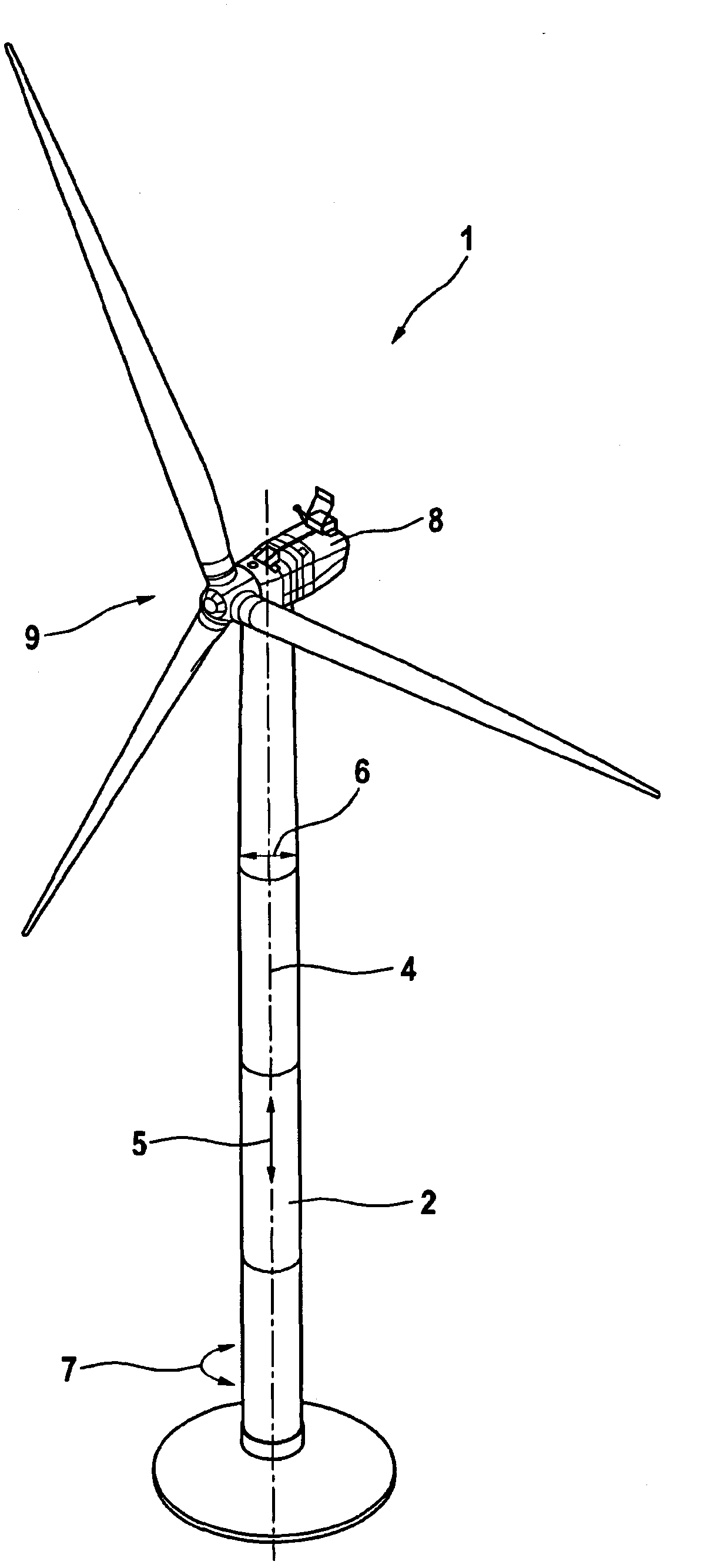
[0057] exist figure 1 shows a wind turbine 1 with a tower 2 , with a machine room 8 mounted on the tower 2 rotatably about a tower axis 4 of the tower 2 , and a rotor shaft arranged in the machine room 8 The generator is connected to the rotor 9. In wind tracking (also called "yaw"), the machine room 8 is rotated in the horizontal plane about the tower axis 4 of the tower 2 so that the rotor 9 rotates perpendicular to the wind and thus maximizes energy production. Due to wind direction changes or even rotations during operation of the wind turbine 1, it is possible that the machine room 8 repeatedly rotates about its own axis.

[0058] The statements axial 5 , radial 6 , circumferential 7 and statements for upper and lower used below are relative to the longitudinal axis of the erected tower 2 of the wind turbine 1 .

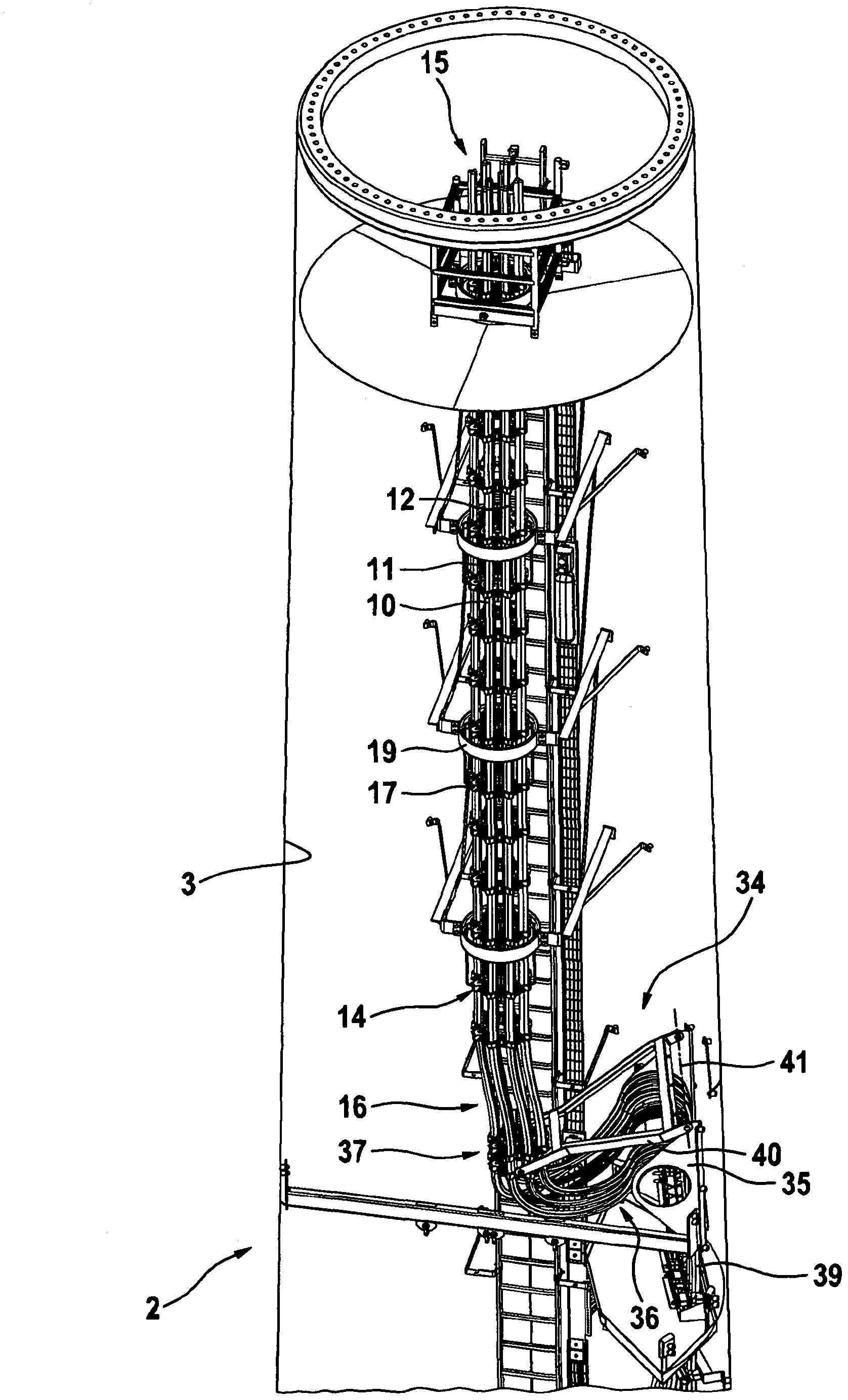
[0059] figure 2 An upper part of a tower 2 of a wind turbine 1 is shown. In the tower 2 of the wind turbine 1 a plurality of current-carrying cables 10 , 1...


PUM


Abstract

The invention relates to a tower for a wind turbine and to a cable guide for a tower of a wind turbine, wherein a machine housing for the wind turbine is arranged on the tower such that it can rotate by means of the azimuth bearing about a vertical axis which runs in the longitudinal direction of the tower. Current-carrying cables, such as power cables, are routed in the tower of the wind turbine out of the machine housing from electrical components to the ground. These comprise a multiplicity of cables, for example a plurality of cables for electrically carrying individual phases of alternating current, in particular three-phase alternating current, cables for ground conductors and/or signal and control cables. One object of the invention is to specify improved routing of the cables which, inter alia, avoids the disadvantages of the prior art.; One particular aim is to ensure that the current load capacity of the cables is ensured, and/or that wear between the cables is reduced. According to the invention, the object is achieved by the features of the main claim 1, by arranging a guide apparatus effectively between the cable loom and the tower, in the tower, for at least partial fixing of the area of the cable loom to the tower, wherein the guide apparatus has means for supporting the lower area of the cable loom in a radial direction, and for support with respect to the tower in a circumferential direction. In this case, the guide apparatus is designed such that the lower area of the cable loom is mounted such that it can move in the axial direction with respect to the tower, but is essentially fixed with respect to the tower in the circumferential and radial directions.

Description

technical field [0001] The invention relates to a tower for a wind turbine and a cable guide for a tower for a wind turbine, wherein a vertical shaft can be wound around the tower on the tower by means of an azimuth bearing The machine room of the wind turbine is arranged in a rotational manner on an axis extending in the longitudinal direction of the frame. A generator for generating electrical energy is arranged in the machine room, which generator can be driven by the rotor of the wind turbine. The azimuth bearing enables a horizontal orientation of the machine room depending on the wind direction, so-called wind tracking of the wind turbine. For the automatic alignment of the machine compartment, one or more azimuth drives are arranged on the azimuth bearings, which are connected in a rotationally fixed manner to the machine frame of the nacelle. In this case, the azimuth bearing must guide the occurring bearing forces, such as thrust, centrifugal and yaw forces, from th...

Claims


Application Information

Patent Timeline
IPC IPC(8): F03D11/00F03D11/04
CPCY02E10/723Y02E10/72F03D11/00H01B9/008F03D11/04Y02E10/728F03D11/0066F03D13/20F03D80/00F03D80/85H02G3/32
Inventor M·多梅斯莱S·施塔克
Owner SUZLON ENERGY LTD
Why Eureka
Try Eureka