Vacuum pump

一种真空泵、泵部的技术,应用在泵、泵装置、泵元件等方向,能够解决没有缓和负荷等问题

Active Publication Date: 2013-02-13
EDWARDS JAPAN
View PDF6 Cites 7 Cited by
  • Summary
  • Abstract
  • Description
  • Claims
  • Application Information

AI Technical Summary

Problems solved by technology

In the case of this structure, the lower side of the joining portion 110b flexes to relieve the load, but in the FRP structure, the vicinity of the end face, which is the weakest, hardly bends, so there is almost no effect of relaxing the load.

Method used


Image

  • Vacuum pump
  • Vacuum pump
  • Vacuum pump

Examples


Embodiment

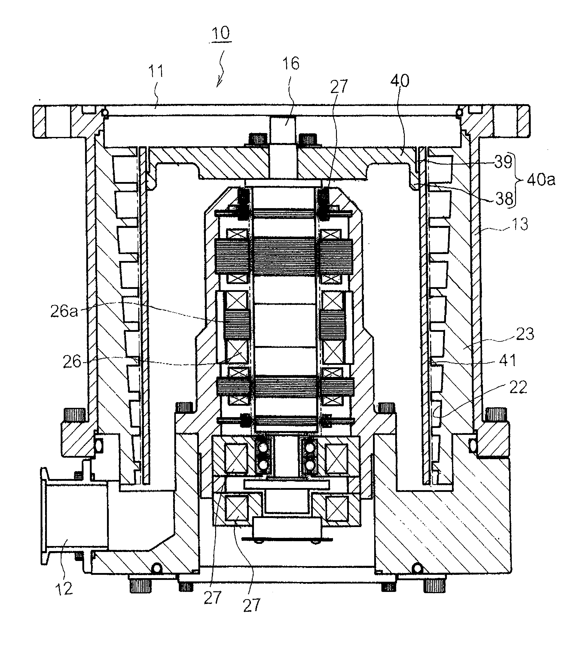
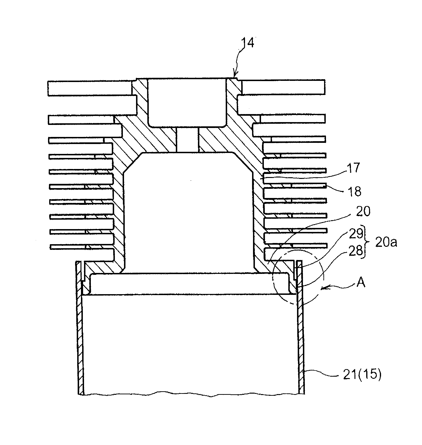
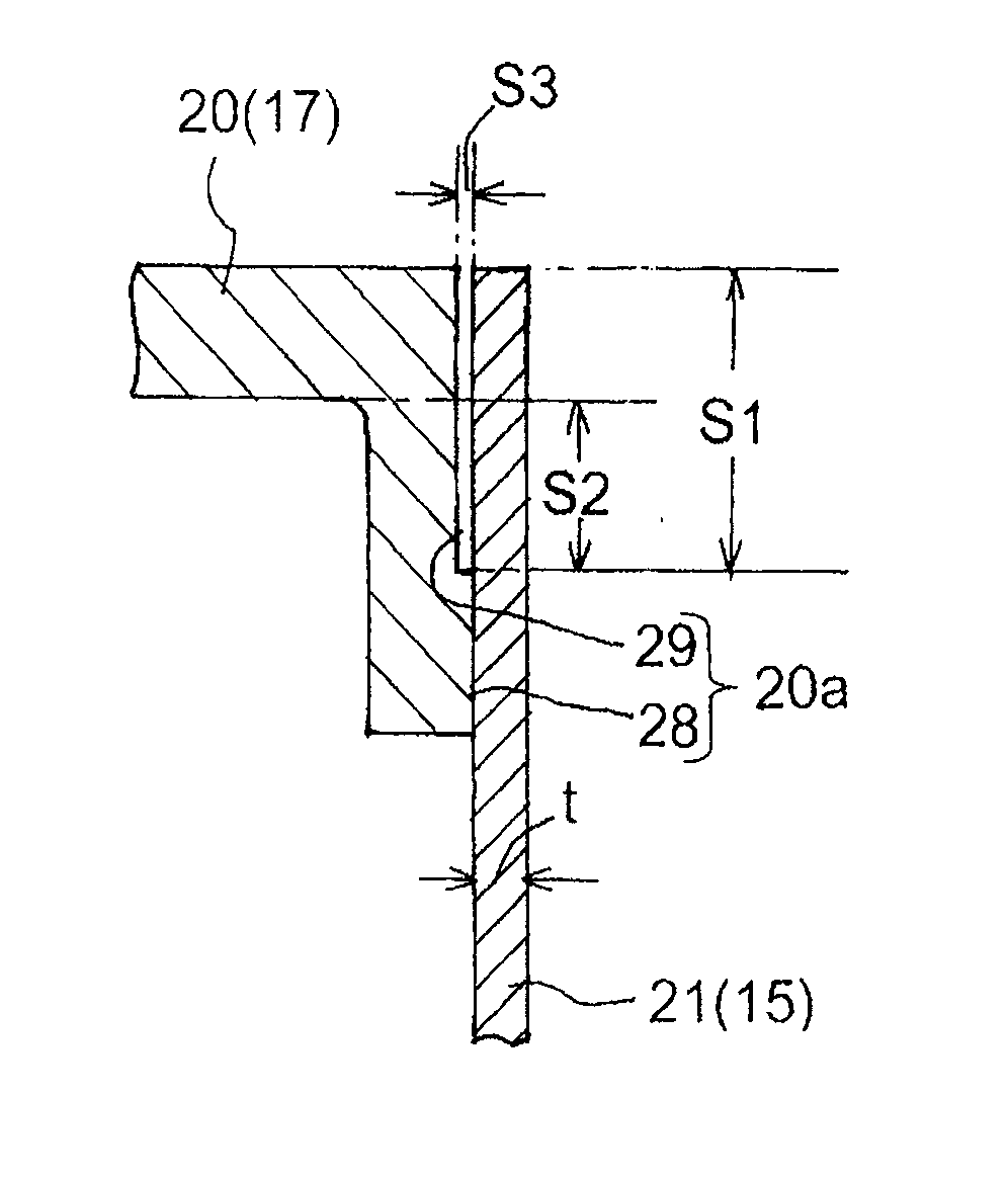
[0044] Hereinafter, preferred embodiments of the compound vacuum pump of the present invention will be described with reference to the drawings. 1 and 2 are diagrams showing a composite vacuum pump related to the present invention, FIG. 1 is a longitudinal sectional view thereof, and FIG. 2 shows a joint structure of a rotor of a turbomolecular pump part of the pump and a cylindrical rotor of a screw groove pump part. 3 is an enlarged sectional view of A portion in FIG. 2 , and FIG. 4 is an exploded longitudinal sectional view showing the joining portion of the rotor of the turbomolecular pump unit shown in FIG. 2 and the cylindrical rotor of the screw groove pump unit.

[0045] In this figure, a composite vacuum pump 10 includes a casing 13 having an air intake port 11 and an exhaust port 12 . Inside the casing 13, a turbomolecular pump part 14 is provided on the upper part, and a cylindrical thread groove pump part 15 is provided below it, and a structure passing through the...


PUM


Abstract

Disclosed is a low-cost composite-type vacuum pump having a strength capable of withstanding high loads and using a cylindrical rotor formed from a fiber-reinforced plastic material. Having a turbomolecular pump unit (14) and a thread groove pump unit (15), the composite vacuum pump is formed by press-fitting a connection part (20a) of a rotor (17) of the turbomolecular pump unit (14) into the upper end of a cylindrical rotor (21) formed from the fiber-reinforced plastic material of the thread groove pump unit (15). The connection part (20a) of the rotor (17) is formed on the bottom end of the rotor (17) integrally with said rotor (17) and in the shape of a cylinder with an L-shaped cross section, and is provided with: a contact part (28) having an outer diameter allowing press-fitting into the inside surface of the cylindrical rotor (21); and a small diameter section (29) positioned above said contact part (28) and, having an outer diameter smaller than the inner diameter of the aforementioned cylindrical rotor (21), capable of being placed inside the cylindrical rotor (21) away from the inner surface of the cylinder rotor (21).

Description

technical field [0001] The present invention relates to a vacuum pump, and more particularly to a vacuum pump usable in a pressure range from low vacuum to high vacuum and ultrahigh vacuum in industrial vacuum devices such as semiconductor manufacturing and high energy physics. Background technique [0002] In this specification, a compound vacuum pump including a turbomolecular pump unit and a thread groove pump unit will be described as an example. Conventionally, such a composite vacuum pump is a longitudinal sectional view of a conventional composite vacuum pump shown in FIG. A structure in which a turbomolecular pump unit 104 and a cylindrical screw groove pump unit 105 are arranged in this order from the side. In addition, FIG. 13 is an enlarged view of part B in FIG. 12 . [0003] In addition, in FIG. 12 , reference numeral 106 is the rotation shaft of the rotor 107 of the turbomolecular pump unit 104 and the cylindrical screw groove pump unit 105 , and 108 is a mot...

Claims


Application Information

Patent Timeline
Patent Type & Authority Applications(China)
IPC IPC(8): F04D19/04
CPCF04D29/644F04D19/046F04D19/042F04D19/044F04D19/04F04D29/02F04D25/16
Inventor 桦泽刚志
Owner EDWARDS JAPAN
Why Eureka
Try Eureka