Mould for optic lens

A technology of optical lenses and molds, which is applied to optical components, household appliances, and other household appliances. It can solve the problems of easy petrification of diamond knives, poor liquid circulation, and increased defective rate, so as to improve deformation, increase yield, and The effect of force balance

Inactive Publication Date: 2013-02-20
YINGTAN YONGWEI PHOTOELECTRIC INSTR
View PDF5 Cites 4 Cited by
  • Summary
  • Abstract
  • Description
  • Claims
  • Application Information

AI Technical Summary

Problems solved by technology

[0002] The production of aspherical lenses by the practical injection method requires high-precision diamond turning methods to produce high-precision injection mold cores with a surface roughness of 25nm or even smaller. Therefore, nickel-plating is often used on the surface of the mold core and then precision is performed with a diamond knife. Processing molds, but although the precision can be more precise, it also solves the problem that diamond knives are easy to petrify, but it is inevitable that when making mold cores, the diamond knives will cause burrs when they are closed, even for existing molds. Kernels are released from the mold at right angles, resulting in difficulty in demoulding
The second is the poor circulation of the poured liquid, these problems will inevitably lead to an increase in the rate of defective products

Method used


Image

  • Mould for optic lens
  • Mould for optic lens
  • Mould for optic lens

Examples


Embodiment Construction

[0017] The present invention will be further described below in conjunction with accompanying drawing:

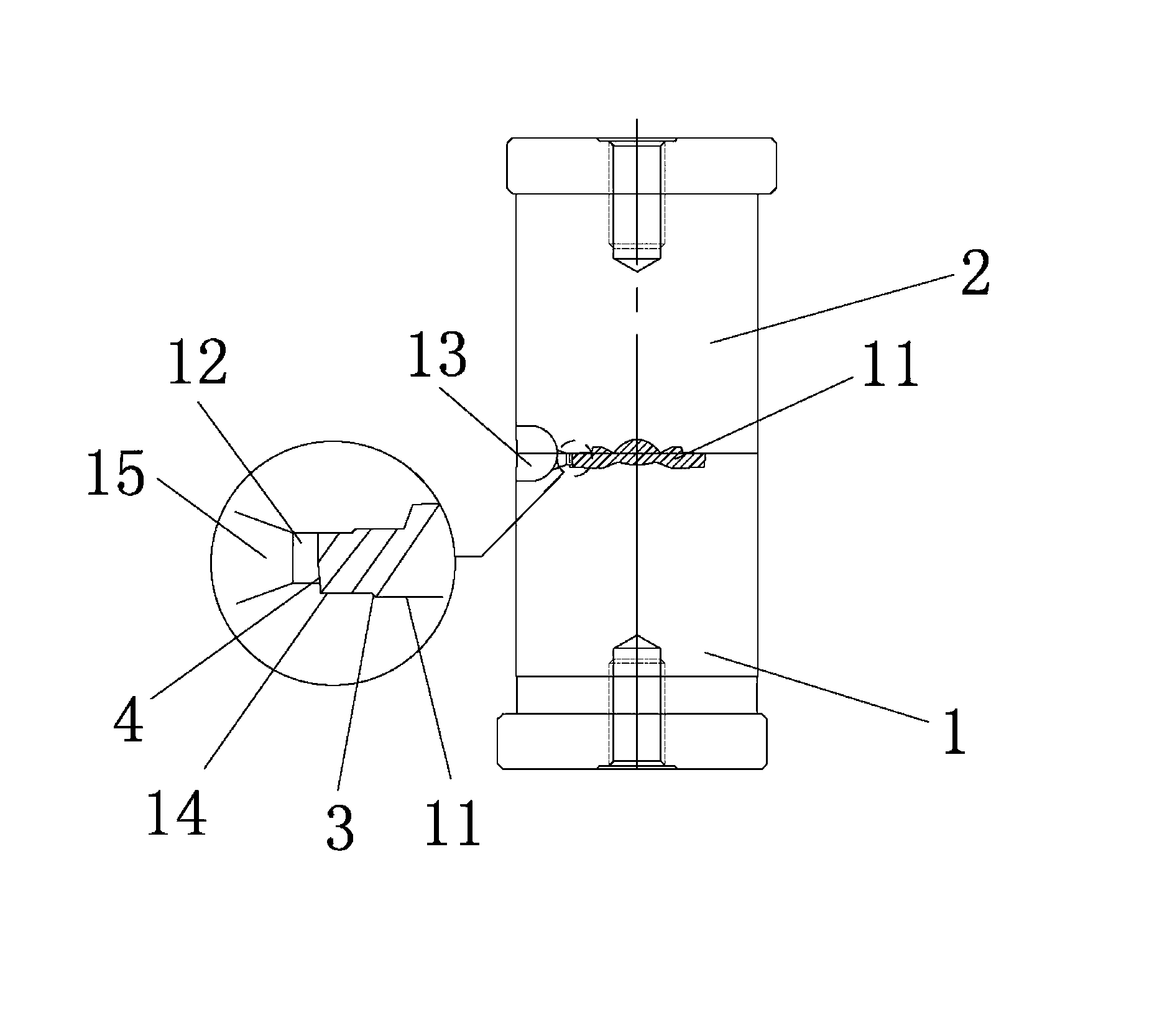
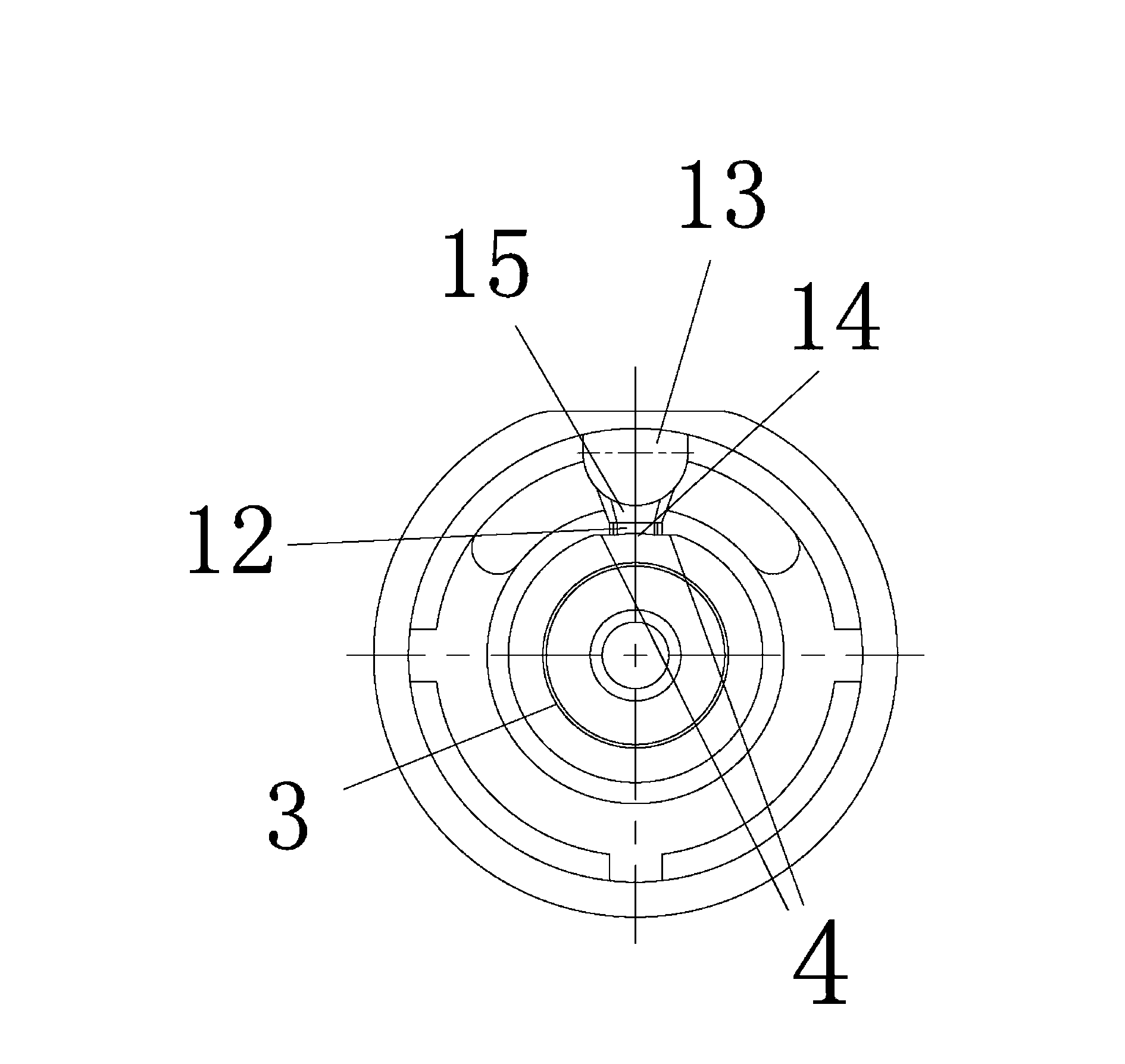
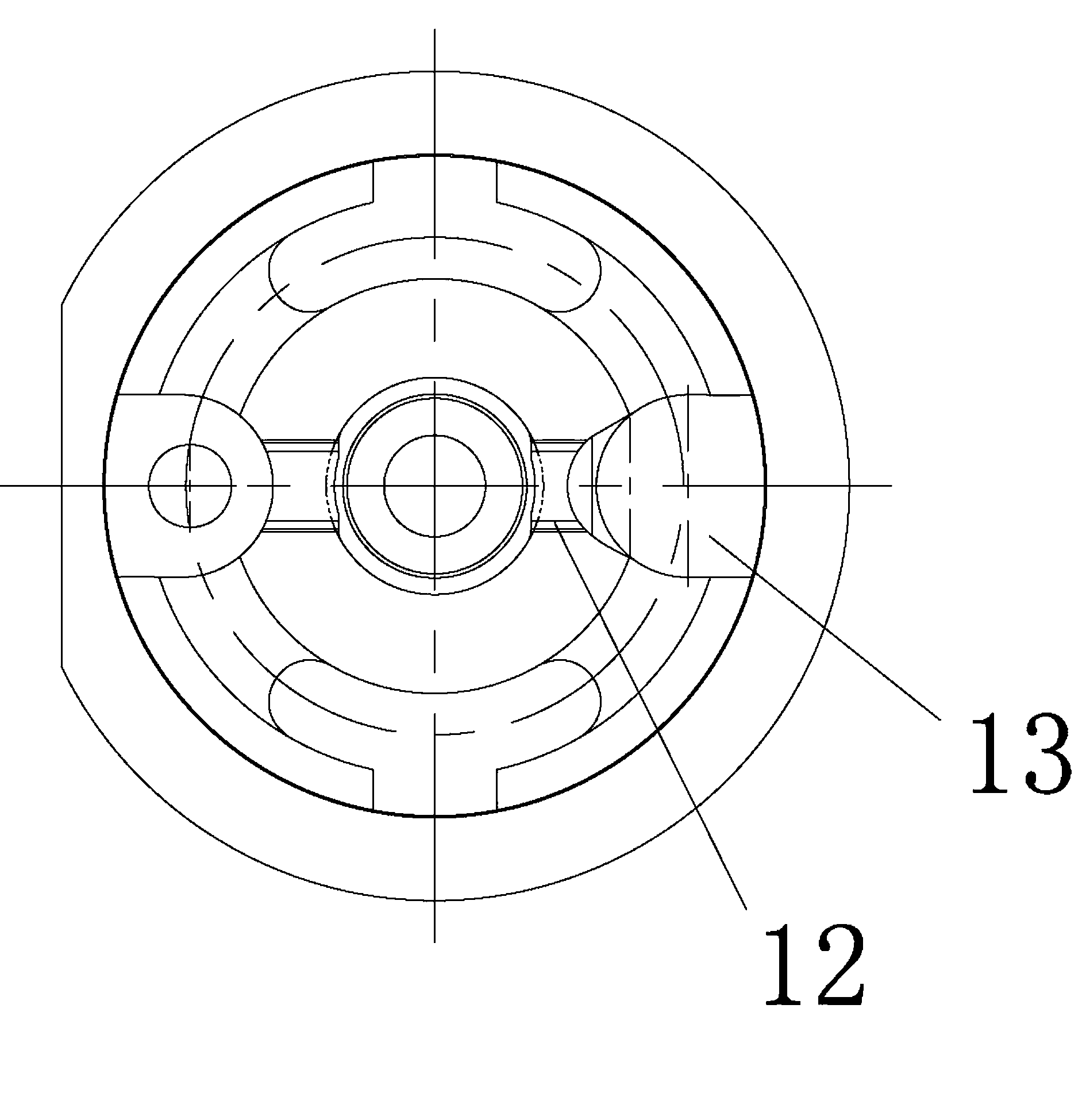
[0018] Optical lens molds, including mold cores, such as figure 1 As shown, the mold core includes a lower mold 1 and an upper mold 2, the end surface of the lower mold 1 forms a top surface, the outer edge of the top surface is surrounded by an edge, and a concave mold cavity 11 is provided in the center of the top surface. The edge of the mold cavity 11 opens a runner 12 toward the edge, and the edge is provided with a gate 13 toward the runner 12, and the intersection edge of the mold cavity 11 and the runner 12 1. A cut-off area 14 is formed between the side walls of the cavity 11 near the two sides of the runner 12, and a connecting channel 15 is connected between the runner 12 and the gate 13; the bottom surface of the cut-off area 14 is connected to the The bottom surface of the mold cavity 11 forms a step 3 at the intersection, and at the step 3 , the level of the ...


PUM


Abstract

The invention provides a mould for an optic lens. The mould comprises an upper mould and a lower mould, wherein the end face of the lower mould forms a top surface, the outer edge around the top surface serves as an edge portion, and an inwards-recessed cavity is arranged at the center of the top surface. A runner and a sprue are sequentially arranged on the edge of the cavity towards the edge portion, an edge cutting area is defined by the intersecting edge of the cavity and the runner and the lateral wall of the cavity close to two sides of the runner, and the runner is communicated with the sprue through a communication channel. A step is formed at the intersecting position of the bottom surface of the edge cutting area and the bottom surface of the cavity, and the horizontal height of the bottom surface of the cavity is lower than that of the bottom surface of the edge cutting area at the position of the step. The edge of the original cavity close to the runner is inclined, so that when ejected, one side of the mould is free of extrusion of the lateral wall, labor is saved, and the product is not damaged. The step is arranged at the bottom of the cavity, and the deckle edge and the assembly face of the manufactured lens are not on the same plane, so that uneven stacking is avoided.

Description

technical field [0001] The invention belongs to the field of optical molds, in particular to a mold for making optical lenses. Background technique [0002] The production of aspherical lenses by the practical injection method requires high-precision diamond turning methods to produce high-precision injection mold cores with a surface roughness of 25nm or even smaller, so nickel-plating is often used on the surface of the mold core and then precision is performed with a diamond knife. Processing molds, but although the precision can be more precise, it also solves the problem that diamond knives are easy to petrify, but it is inevitable that when making mold cores, the diamond knives will cause burrs when they are closed, even for existing molds. Kernels are released from the mold at right angles, resulting in difficulty in demoulding. The second is the poor circulation of the poured liquid, and these problems will inevitably lead to an increase in the rate of defective pro...

Claims


Application Information

Patent Timeline
Patent Type & Authority Applications(China)
IPC IPC(8): B29C45/26B29L11/00
Inventor 叶文俊欧益铭
Owner YINGTAN YONGWEI PHOTOELECTRIC INSTR
Why Eureka
Try Eureka