Mechanical and electrical integrated interlocking control device

A control device and an integrated technology, applied in non-mechanical transmission-operated locks, building locks, buildings, etc., can solve the problems of no mutual control function, blank control device, low anti-theft performance, etc., to prevent unauthorized unlocking and broad application prospects Effect

Inactive Publication Date: 2013-02-20
大连鼎信机电技术有限公司
View PDF5 Cites 1 Cited by
  • Summary
  • Abstract
  • Description
  • Claims
  • Application Information

AI Technical Summary

Problems solved by technology

[0002] Mechatronic control devices are widely used at present, but control devices that can realize the interlocking of machinery and electronics are still blank
Especially for vehicle-mounted cabinets (such as tank trucks, escort vehicles, etc.), vehicle-mounted safes, and various important warehouse doors that require internal and external dual safety control, it is relatively difficult to open or close mechanical mechanisms controlled by electronic or software systems. Easy, but there is no mechanical mechanism to reversely control the electronic or software system, that is, there is no mutual control function, which makes the anti-theft performance of these important safe places extremely low, prone to internal theft and difficult to obtain evidence. This has always been an industry effort. Tackling but unresolved problems

Method used


Image

  • Mechanical and electrical integrated interlocking control device
  • Mechanical and electrical integrated interlocking control device
  • Mechanical and electrical integrated interlocking control device

Examples


Embodiment 1

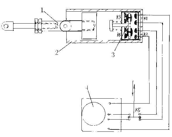
[0019] like figure 1 The electromechanical interlock control device includes a mechanical mechanism and an electric mechanism. The mechanical mechanism and the electric mechanism 4 are connected through a two-way pressure-touch switch 3 and a control switch K5. Installed at the bottom position in the secret room 2, a reciprocating driving rod 1 is installed in the secret room, and the driving rod is connected to the mechanical mechanism. The mechanical mechanism is the door body 6 of the safety device 7. Hinged driving rod 1, the reciprocating driving rod 1 in the closed room cooperates with the two-way pressure touch switch 3 to open and close, so that the pressure touch switch produces on and off actions, and the two-way pressure touch switches K1 and K2 are respectively connected to open the circuit and lock circuit, the opening circuit and the locking circuit are connected in parallel through the control switch K5 and control each other to switch power transmission. The e...

Embodiment 2

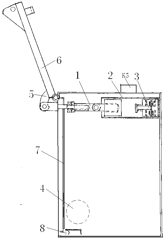
[0021] like figure 2 The electromechanical interlock control device includes a mechanical mechanism and an electric mechanism 4. The mechanical mechanism and the electric mechanism 4 are connected through a two-way pressure switch 3 and a control switch K5. The two-way pressure switches are respectively set on the control circuit of the controller. The switch is installed at the bottom position in the secret room 2, and a reciprocating driving rod 1 is installed in the secret room, and the driving rod is connected to a mechanical mechanism. The upper hinged driving rod 1, the reciprocating driving rod in the closed room cooperates with the opening and closing of the two-way pressure-touch switch, so that the pressure-touch switch produces on and off actions, and the two-way pressure-touch switches K1 and K2 are respectively connected to the opening circuit and the locking circuit , the opening circuit and the locking circuit are connected in parallel through the control switc...

Embodiment 3

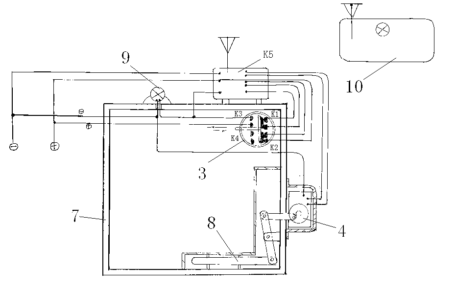
[0023] The device described in Embodiment 2 is used in conjunction with the remote console 10, the controller is connected with the remote control system signal, the remote control system sends an instruction input controller, the controller signal controls the opening circuit or the locking circuit to communicate, and the controllers respectively When unlocking or locking, switch and send power to the opening circuit and locking circuit, and the opening circuit or locking circuit drives the electric mechanism to run forward or reverse to realize opening or locking.

[0024] When the above-mentioned embodiment 1-3 is running with the door open, the box body is provided with a pressure-touch switch combination, a controller and a warning light in the secret room, and the door control driving rod reciprocates in the secret room, and the reciprocating driving rod in the secret room and the two-way pressing The opening and closing cooperation of the touch switch makes the pressure ...


PUM


Abstract

The invention relates to an interlocking control device. A mechanical and electrical integrated interlocking control device comprises a mechanical mechanism and an electric mechanism which are connected through two-way press contact switches and a control switch. The two-way press contact switches are installed at the bottom in a back room, and a drive rod capable of moving in a reciprocating mode is movably installed in the back room and connected with the mechanical mechanism. The drive rod capable of moving in a reciprocating mode in the back room is matched with the two-way press contact switches in an opening and closing mode, the two-way press contact switches K1 and K2 are connected with an opening circuit and a locking circuit respectively which are connected in parallel through the control switch and controlled to be switched mutually to transmit power, and the control switch is connected with the two-way press contact switch K1 or K2 which is controlled by the K1 or K2. According to the mechanical and electrical integrated interlocking control device, the structure is simple, opening and closing motions of mechanical mechanisms of doors and the like are used for forming interlocking with controllers of electric mechanisms, and accordingly, the mutual restriction of mechanical motions and electric mechanisms is achieved.

Description

technical field [0001] The present invention relates to control devices, in particular to interlock control devices. Background technique [0002] The electromechanical integrated control device is widely used at present, but the control device that can realize the interlocking of machinery and electronics is still blank. Especially for vehicle-mounted cabinets (such as tank trucks, escort vehicles, etc.), vehicle-mounted safes, and various important warehouse doors that require internal and external dual safety control, it is relatively difficult to open or close mechanical mechanisms controlled by electronic or software systems. Easy, but there is no mechanical mechanism to reversely control the electronic or software system, that is, there is no mutual control function, which makes the anti-theft performance of these important safe places extremely low, prone to internal theft and difficult to obtain evidence. This has always been an industry effort. Tackling but unresol...

Claims


Application Information

Patent Timeline
Patent Type & Authority Applications(China)
IPC IPC(8): E05B47/00E05B17/22
Inventor 赵忠杜长义袁向群
Owner 大连鼎信机电技术有限公司
Why Eureka
Try Eureka