Cam profile detection system
A detection system, cam profile technology, applied in measuring devices, instruments, optical devices, etc., can solve the problem of not being able to adapt to cam automatic line production, etc., and achieve the effect of good system dynamic performance, high measurement accuracy and fast speed
- Summary
- Abstract
- Description
- Claims
- Application Information
AI Technical Summary
Problems solved by technology
Method used
Image
Examples
Embodiment 1)
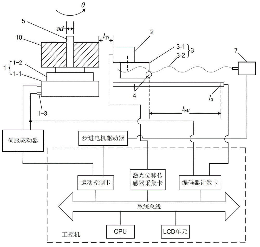
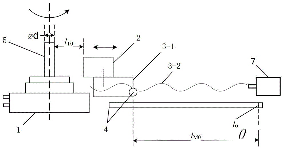
[0019] see Figure 1-2 , The cam profile detection system based on the direct drive motor of this embodiment includes: a direct drive motor 1 for driving the cam 10 to rotate horizontally and coaxially around a vertical spindle 5, which is arranged horizontally on the side of the direct drive motor 1 The screw nut pair 3 of the screw nut pair 3, the laser measuring head set on the movable nut 3-1 of the screw nut pair 3 and on the side of the cam 10, the grating used to measure the horizontal displacement of the movable nut 3-1 The ruler displacement sensor 4, a circular grating for detecting the rotation angle of the cam 10 and an industrial computer arranged in the fixed seat 1-1 of the direct drive motor 1, and an industrial computer; the industrial computer controls the direct drive motor 1 and the wire The lever nut pair 3 moves, and the outer contour data of the cam 10 is obtained according to the data measured by the laser measuring head 2, the grating scale displacement...
Embodiment 2)
[0043] On the basis of Embodiment 1, this embodiment has the following modifications:
[0044] In order to eliminate the influence of the machining or installation error of the spindle 5 on the accuracy of the cam profile detection, the detection method of the cam profile detection system includes:
[0045] A. Detect the outer edge data of the mandrel 5: when the mandrel 5 starts to rotate one circle, the distance between the laser measuring head 2 and the outer circle of the mandrel 5 is the first distance Always control within the range of the laser measuring head 2, while detecting and recording the rotation angle θ i Corresponding first spacing , And the mover 3-1 is horizontally aligned with the hard zero The second distance ;
[0046] B. Fit the cam 10 on the spindle 5 without clearance, if the outer contour data of the cam 10 is known , While starting to control the cam 10 to rotate one circle, control the laser measuring head 2 relative to the outer contour of the cam 10 ...
PUM
 Abstract
Description
Claims
Application Information
 - R&D
- Intellectual Property
- Life Sciences
- Materials
- Tech Scout
- Unparalleled Data Quality
- Higher Quality Content
- 60% Fewer Hallucinations
Browse by: Latest US Patents, China's latest patents, Technical Efficacy Thesaurus, Application Domain, Technology Topic, Popular Technical Reports.
© 2025 PatSnap. All rights reserved.Legal|Privacy policy|Modern Slavery Act Transparency Statement|Sitemap|About US| Contact US: help@patsnap.com


