Average linear LED (Light Emitting Diode) drive circuit

A LED driving and linear technology, applied in the direction of lamp circuit layout, electric light source, electrical components, etc., can solve the problems of reduced driving circuit efficiency and system failure, and achieve the effects of reduced power consumption, high conversion efficiency, and improved efficiency

Inactive Publication Date: 2013-02-20
SHANGHAI BRIGHT POWER SEMICONDUCTOR CO LTD
View PDF5 Cites 12 Cited by
  • Summary
  • Abstract
  • Description
  • Claims
  • Application Information

AI Technical Summary

Problems solved by technology

The main disadvantage of this kind of LED drive circuit is that in the case of high input voltage, the current sink 2 produces a large voltage drop, which reduces the efficiency of the drive circuit, and generates large heat on the current sink 2, which is likely to cause system damage. fail

Method used


Image

  • Average linear LED (Light Emitting Diode) drive circuit
  • Average linear LED (Light Emitting Diode) drive circuit
  • Average linear LED (Light Emitting Diode) drive circuit

Examples


Embodiment Construction

[0020] Specific embodiments of the present invention will be described in detail below with reference to the accompanying drawings.

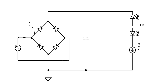
[0021] In order to solve the technical problems that the LED driving circuit in the prior art has low efficiency and is prone to system failure, the present invention proposes an average linear LED driving circuit. The average linear LED drive circuit directly connects a filter capacitor in parallel with both ends of the LED load. When the rectified input voltage is slightly higher than the filter capacitor voltage, current flows through the power switch. When the rectified input voltage is higher than the filter capacitor voltage For a long time, the current in the power switch is reduced or even turned off, and the average value of the current in the power switch is equal to the LED load current, thereby realizing the purpose of high-efficiency LED driving.

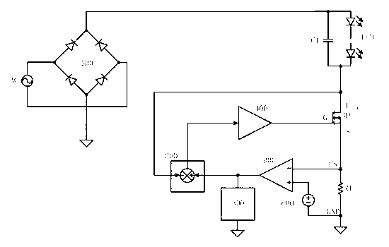
[0022] like figure 2 shown in, figure 2 It is a schematic structural diagram of ...


PUM


Abstract

The invention discloses an average linear LED (Light Emitting Diode) drive circuit comprising a rectifier bridge, an LED load, a compensation network and a voltage feedback network, wherein the rectifier bridge is connected with an input alternating voltage; and the LED load is connected with a filter capacitor in parallel and then connected to a power switch. When the output direct voltage of the rectifier bridge is higher than the voltage of the filter capacitor, the drain voltage of the power switch raises, the current in the power switch is reduced or switched off through the feedback network, and the current average value in the power switch is enabled to be equal to the current of the LED load through the compensation network. According to the average linear LED drive circuit provided by the invention, the current of the drive circuit can be intelligently controlled, so that the power consumption of a system is reduced, and the efficiency is improved. The drive circuit is capable of keeping higher conversion efficiency under the condition of higher input voltage in particular.

Description

[0001] technical field [0002] The invention relates to an LED driving circuit, in particular to a high-efficiency constant-current average linear LED driving circuit. Background technique [0003] The LED light source has the advantages of energy saving and environmental protection. However, the technical difficulty in the application of the LED light source is that the control circuit is unstable, which greatly reduces the life of the LED. At present, the failure of LED lighting fixtures is largely caused by the unreasonable structure of the LED drive circuit. The linear LED driving circuit used in the prior art is such as figure 1 As shown, the AC power is rectified by the rectifier bridge 1 and then filtered by the capacitor C1 to generate a DC power supply. The DC power supply is connected to the LED load, and the negative terminal of the LED load is connected to a current sink 2, which keeps the current of the LED load constant. The main disadvantage of this kind...

Claims


Application Information

Patent Timeline
Patent Type & Authority Applications(China)
IPC IPC(8): H05B37/02H05B44/00
CPCY02B20/348H05B33/0812H05B37/02H05B45/395Y02B20/30
Inventor 孙顺根于得水杨彪
Owner SHANGHAI BRIGHT POWER SEMICONDUCTOR CO LTD
Why Eureka
Try Eureka