Squeezing unit for a strip rolling mill and strip rolling mill

A pressing machine and rolling mill technology, applied in the direction of metal rolling mill stand, metal rolling stand, roll, etc., can solve the problem of fast wear of pressure roll, achieve good extrusion degreasing, and minimize downtime

Active Publication Date: 2013-02-20
瓜奈里科技股份有限公司
View PDF8 Cites 1 Cited by
  • Summary
  • Abstract
  • Description
  • Claims
  • Application Information

AI Technical Summary

Problems solved by technology

Of course, the pressure rollers wear out relatively quickly, m

Method used


Image

  • Squeezing unit for a strip rolling mill and strip rolling mill
  • Squeezing unit for a strip rolling mill and strip rolling mill
  • Squeezing unit for a strip rolling mill and strip rolling mill

Examples


Embodiment Construction

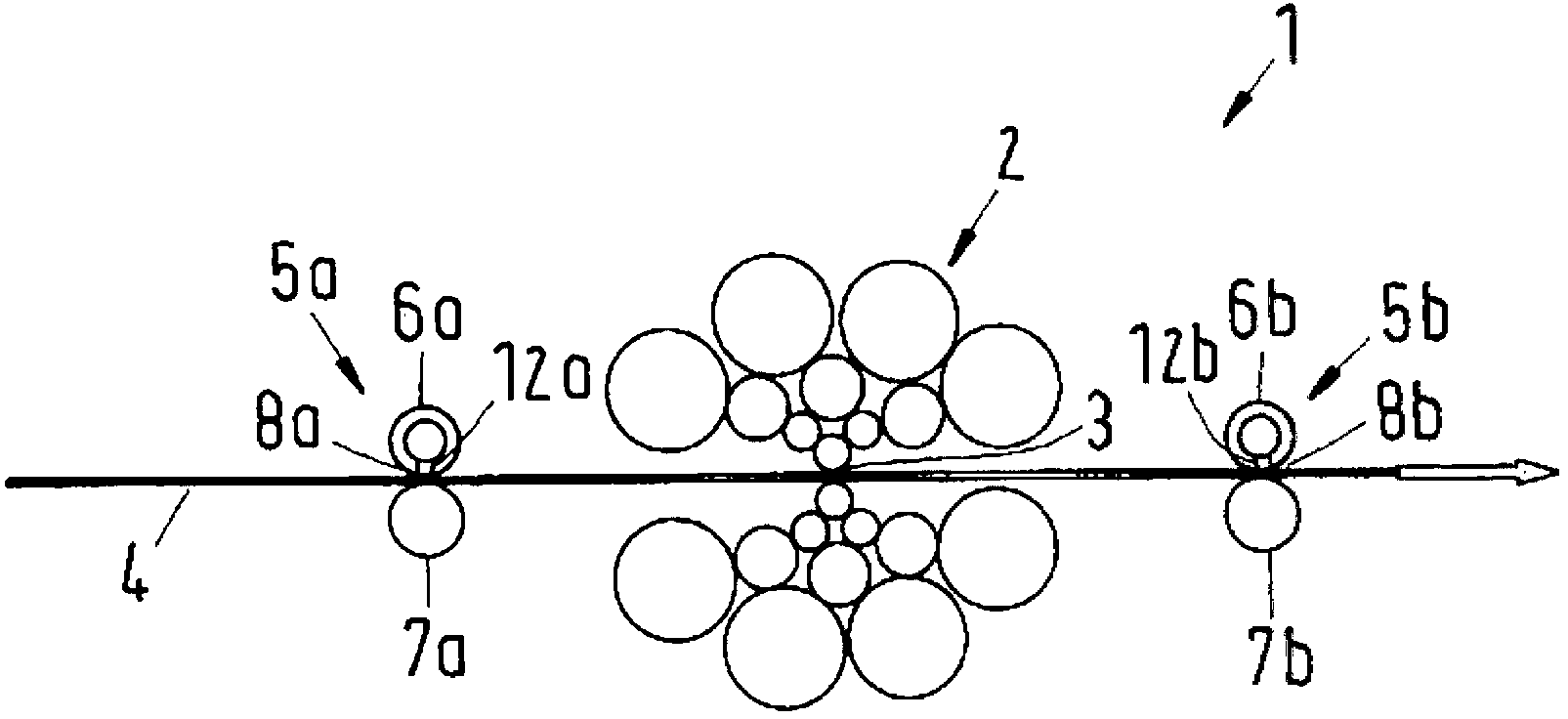
[0030] exist figure 1 A strip mill 1 is schematically illustrated in FIG. 2 with a multi-roll rolling installation 2 having a press nip 3 through which a metal strip 4 is guided. The metal belt can be guided through the press nip 3 in alternating directions, wherein the press nip 3 is narrowed before each changeover. In this way, a reduction in the thickness of the metal strip 4 is achieved. The metal strip 4 is a high-grade steel strip in this embodiment.

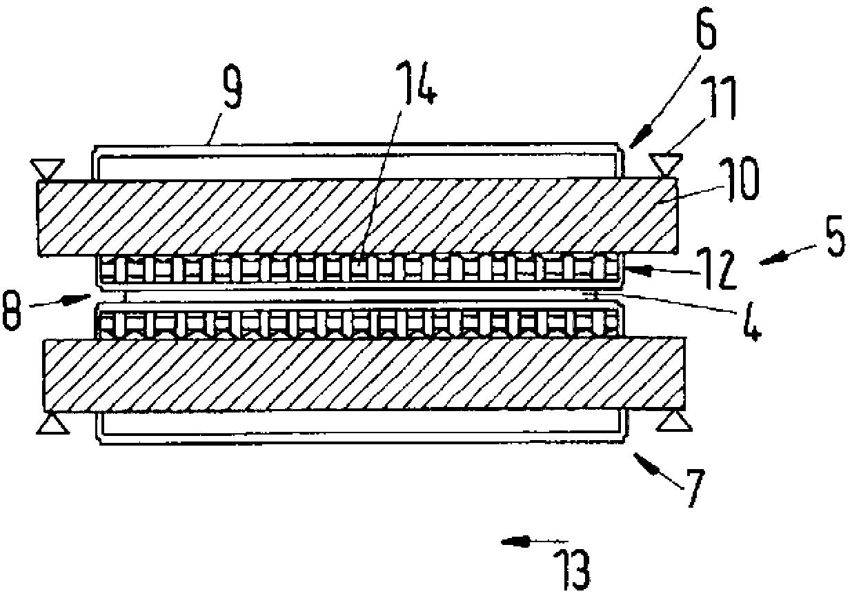
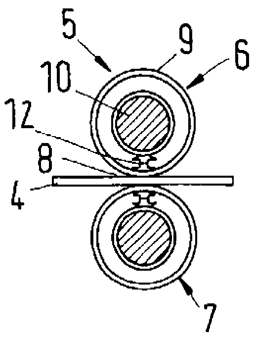
[0031] To cool the metal strip 4 , oil is applied by means of an application device (not shown) before the pressing gap 3 . A press 5 a , 5 b of identical design is arranged on both sides of the press nip 3 for oil removal. The presses 5a, 5b have upper press rolls 6a, 6b and lower press rolls 7a, 7b, between which a press nip 8a, 8b is formed between which the metal strip 4 is guided pass through it. A winding station (not shown) is arranged in each case on the side of the presses 5a, 5b facing away from the press ni...


PUM

PropertyMeasurementUnit
Outer diameteraaaaaaaaaa

Abstract

The invention relates to a squeezing unit (5) for a strip rolling mill and to a strip rolling mill comprising such a squeezing unit, wherein the squeezing unit (5) has an upper roller (6) and a lower roller (7), between which a squeezing nip (8) is formed. To achieve long service lives, ensure low residual moisture and minimize surface damage on the strip, at least one of the rollers (6, 7) is provided with a revolving shell (9) and a stationary yoke (10), which passes axially through the shell (9), wherein a pressing device (12) is arranged between the yoke (10) and the shell (9). The pressing device (12) subjects the shell (9) to an outward bearing pressure in a radial direction, wherein the bearing pressure is variable over a roller width such that zonal control and active width adjustment are effected.

Description

technical field [0001] The invention relates to a press for a strip rolling mill with an upper press roll and a lower press roll between which a press nip for guiding a metal strip is formed. Furthermore, the invention relates to a strip mill for cold rolling metal strip, in particular special steel strip, with a press of this type. Background technique [0002] During the cold rolling of metal strips, in particular special steel strips, the thickness of the metal strip is reduced by applying pressure to the metal strip, for example between two coiling stations of a multi-roll rolling plant. Such a multi-roll rolling installation is known, for example, from EP 0693328 A1. [0003] Here the metal strip is unwound from one coiling station, passed through a press nip in a multi-roll rolling plant and coiled up at another coiling station. Just before the metal belt is fully unfolded, the metal belt is held and the pressing gap is narrowed. The metal belt then passes through t...

Claims


Application Information

Patent Timeline
IPC IPC(8): B21B1/36B21B3/02B21B13/14B21B45/02F16C13/00B21B27/05
CPCB21B3/02B21B13/147F16C13/028B21B27/055
Inventor E.施尼德M.德拉瓦
Owner 瓜奈里科技股份有限公司
Why Eureka
Try Eureka