Magnetic valve with compact structure, good tightness and high reliability

A compact and airtight technology, applied in the field of solenoid valves, can solve the problems of solenoid valve usage occasions and service life limitations, solenoid valve closing performance cannot be guaranteed, product quality is difficult to be completely guaranteed, etc., to reduce production quality control costs , Good closing and sealing performance, compact structure

Inactive Publication Date: 2013-02-27
李志红
View PDF9 Cites 13 Cited by
  • Summary
  • Abstract
  • Description
  • Claims
  • Application Information

AI Technical Summary

Problems solved by technology

[0005] The purpose of the present invention is to solve the structural defects of some solenoid valves on the existing market. First, the closure is unreliable and easy to leak under the condition of low water pressure 0-0.02MPa. The relevant solenoid valve standard stipulates that the effective working pressure range of the solenoid valve is 0.02 -0.8MPa. It can be seen that the closing performance of the solenoid valve in the low pressure range of 0-0.02 cannot be guaranteed; the production of existing products is through strict control of parts manufacturing and assembly accuracy, and strict testing to ensure product performance, which greatly increases the difficulty of production and assembly, but The product quality is difficult to be completely guaranteed; the second is that there are strict requirements for the particulate impurities in the water and aqueous solution flowing through the solenoid valve, and the particulate impurities are easy to block the water inlet of the pressure control chamber diaphragm, making the solenoid valve control invalid; making the electromagnetic valve use occasion and The problem that the service life is greatly limited

Method used


Image

  • Magnetic valve with compact structure, good tightness and high reliability
  • Magnetic valve with compact structure, good tightness and high reliability
  • Magnetic valve with compact structure, good tightness and high reliability

Examples


Embodiment Construction

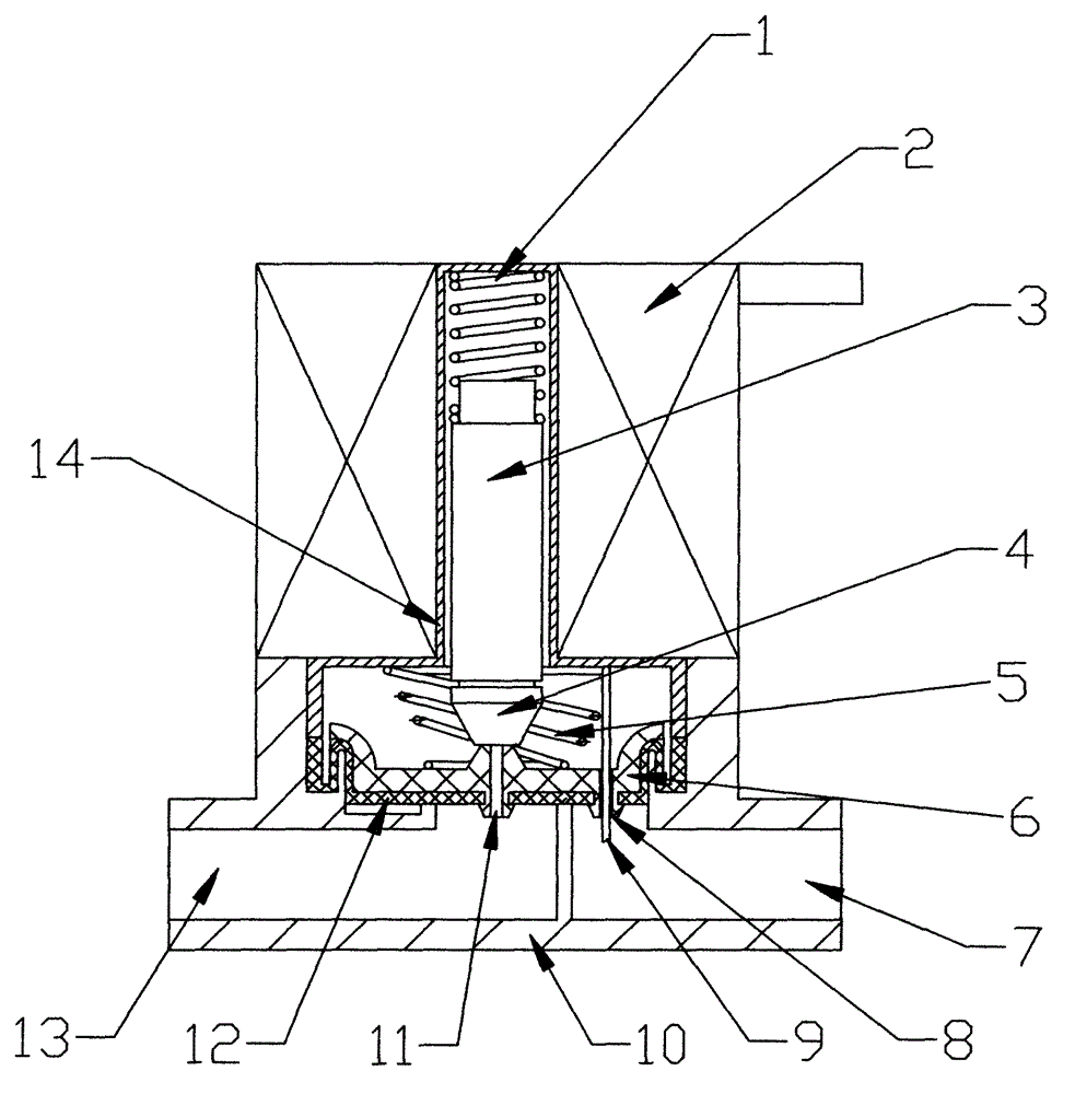
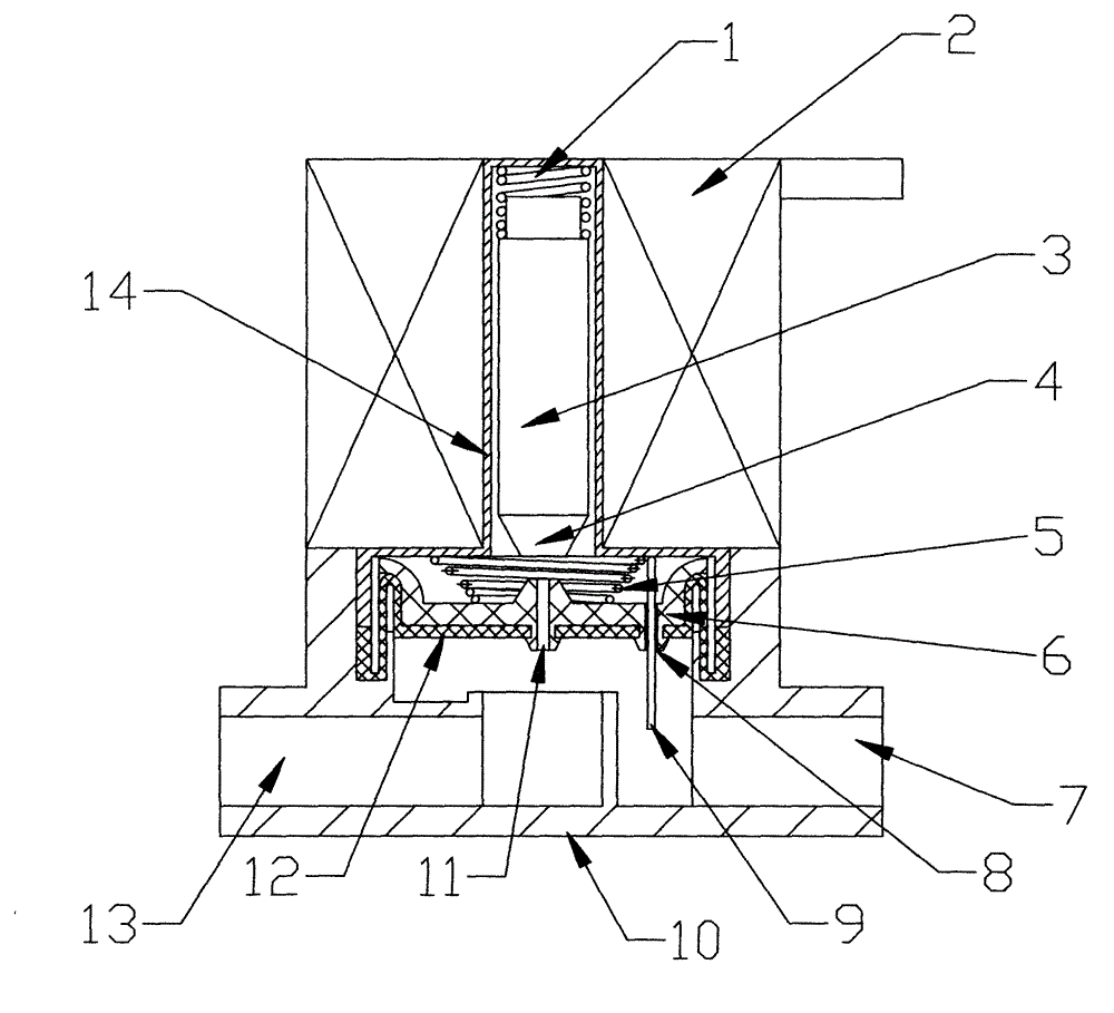
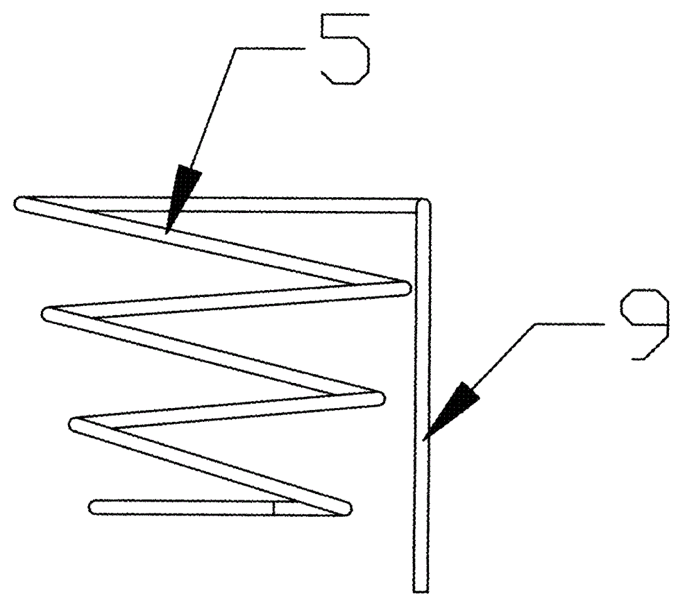
[0013] Below in conjunction with accompanying drawing and embodiment the present invention will be further described:

[0014] As shown in the figure, the present invention includes a body, and the body includes a valve seat 10, a coil 2 disposed on the valve seat 10, a valve core sleeve 14 disposed in the coil 2 and a valve core disposed in the valve core sleeve 14 3. The right side of the lower part of the valve seat 10 is the valve water inlet 7, and the left side of the lower part of the valve seat 10 is the valve water outlet 13. There are a plastic diaphragm 6 and a rubber diaphragm 12, the plastic diaphragm 6 is arranged on the top of the rubber diaphragm 12, and the plastic diaphragm 6 and the rubber diaphragm 12 are fixed together, and the lower part of the valve core 3 is provided with The rubber sealing head 4 is provided with a spool return spring 1 on the top of the spool 3, the right part of the plastic diaphragm 6 is provided with a pressure control chamber wate...


PUM


Abstract

The invention discloses a magnetic valve with a compact structure, good tightness and a high reliability. The magnetic valve comprises a body, the body comprises a valve seat, a coil arranged on the valve seat and a valve element sleeve arranged in the coil and a valve element arranged in the valve element sleeve, a valve water inlet is arranged on the right side on the lower portion of the valve seat, a valve water outlet is arranged on the left side on the lower portion of the valve seat, a plastic diaphragm and a rubber diaphragm are arranged between the coil and the valve seat and on the lower portion of the valve element sleeve, the plastic diaphragm is arranged on the upper portion of the rubber diaphragm, the plastic diaphragm and the rubber diaphragm are fixed together, a rubber seal head is arranged on the lower portion of the valve element, a valve element reset spring is arranged on the upper portion of the valve element, a pressure control cavity water inlet is arranged on the right portion of the plastic diaphragm, a pressure control cavity water outlet is arranged in the middle of the plastic diaphragm, the pressure control cavity water inlet is opposite to the pressure control cavity water outlet, and a tower-shaped with an unclogging pin is arranged between the plastic diaphragm and the valve element sleeve.

Description

technical field [0001] The invention relates to a solenoid valve, in particular to a solenoid valve with compact structure, good sealing performance and high reliability. Background technique [0002] Solenoid valves are widely used as key components of automatic control, but due to structural defects, firstly, they are unreliable to close and easy to leak under low water pressure of 0-0.02MPa. The relevant solenoid valve standards stipulate that the effective working pressure range of solenoid valves is 0.02 ~0.8MPa. It can be seen that the closing performance of the solenoid valve in the low pressure range of 0-0.02 cannot be guaranteed; the production of existing products is through strict control of parts manufacturing and assembly accuracy, and strict testing to ensure product performance, which greatly increases the difficulty of production and assembly, but Product quality is difficult to be completely guaranteed. [0003] The second is that there are strict require...

Claims


Application Information

Patent Timeline
Patent Type & Authority Applications(China)
IPC IPC(8): F16K7/17F16K31/06
Inventor 李志红
Owner 李志红
Why Eureka
Try Eureka