
Step-control mechanical sampling device

A mechanical sampling and step control technology, applied in the direction of sampling devices, etc., can solve problems such as low work efficiency, no power source for sampling tools, and sample representative damage, etc., to achieve automation, improve sampling operating environment, and improve work efficiency Effect

Inactive Publication Date: 2013-02-27
TECHN CENT FOR SAFETY OF INDAL PRODS TIANJIN ENTRY EXIT INSPECTION QUARANTINE BUREAU
View PDF6 Cites 16 Cited by
  • Summary
  • Abstract
  • Description
  • Claims
  • Application Information

AI Technical Summary

Problems solved by technology

[0002] In the quality monitoring process of chemical raw materials, the content of chemical raw materials will be agreed and controlled. The sampling of chemical raw materials is the process of confirming whether the content of chemical mineral products meets the agreement and commitment. There are many chemical and chemical raw materials containing toxic , Harmful and irritating chemical properties are likely to cause harm to the health of laboratory personnel. Therefore, sampling of flakes, granules, and powdered chemical raw materials should avoid manual operation and be carried out under fully enclosed conditions. Therefore, the design of the sampler is very important. Traditional The current sampling tool has the following disadvantages: 1. The sampling tool has no power source, and the manual sampling method is time-consuming and labor-intensive, and the work efficiency is low
2. When sampling chemical raw materials packed in bags, sometimes it is impossible to obtain samples from the inside of the raw materials because the raw materials are squeezed too hard
3. When chemical raw materials are exposed to air during the process of taking them out, the representativeness of the samples taken will be damaged to varying degrees. 4. When laboratory personnel come into contact with toxic, harmful and pungent chemical samples, they will inevitably be affected. varying degrees of injury

Method used


Image

  • Step-control mechanical sampling device
  • Step-control mechanical sampling device
  • Step-control mechanical sampling device

Examples


Embodiment Construction

[0040] In order to understand the present invention more clearly, describe the present invention in detail in conjunction with accompanying drawing and embodiment:

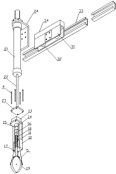
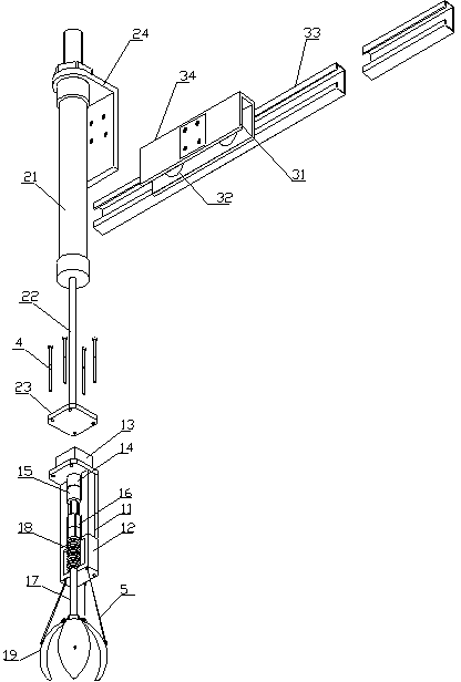
[0041] Such as Figure 1 to Figure 10 As shown, the step-controlled mechanical sampling device is composed of a structural part and a control part, and the structural part includes a sampler assembly 1, a cylinder assembly 2 and a sample delivery assembly 3;

[0042] The sampler assembly 1 is composed of a transition bracket 11, a spring seat 12, a stepper motor 13, a coupling 14, a drive screw nut 15, a drive screw 16, a sampling arm 17, a spring 18 and a sampling head 19;

[0043] The transitional bracket 11 is used as the intermediate support body connecting the spring seat 12 and the stepping motor 13. Its upper part is a plane, and the upper part of the center is processed with a round hole 111 for placing the drive screw nut 15. The central lower part of the transitional bracket 11 is processed wit...


PUM


Abstract

The invention relates to a step-control mechanical sampling device. The device is characterized in that a structure portion comprises a sampler component, an air cylinder component and a sample delivery component. The sampler component is composed of a transition support, a spring seat, a step motor, a coupling, a transmission screw nut, a transmission screw, a sampling arm, a spring and a sampling head. A switching power supply supplies DC24V power for a plane diaphragm pressure sensor at the lower end of the connection disc, the plane diaphragm pressure sensor outputs current signals in a range of 4mA to 20mA according to pressure imposed by a sample, and the current signals in a range of 4mA to 20mA acquired through the plane diaphragm pressure sensor are subjected to analog-to-digital (AD) conversion and sent to a single chip microcomputer to be processed to output pulse control signals. The pulse control signals are output to a FD5-3 five-phase step motor driving controller which controls the action of the step motor, and accordingly, the step-control mechanical sampling is achieved.

Description

technical field [0001] The invention relates to chemical raw material sampling equipment, in particular to a step-controlled mechanical sampling device, which is suitable for sampling chemical raw materials of toxic, harmful and pungent chemical properties such as flakes, granules, powders, and solid chemical raw materials. Background technique [0002] In the quality monitoring process of chemical raw materials, the content of chemical raw materials will be agreed and controlled. The sampling of chemical raw materials is the process of confirming whether the content of chemical mineral products meets the agreement and commitment. There are many chemical and chemical raw materials containing toxic , Harmful and irritating chemical properties are likely to cause harm to the health of laboratory personnel. Therefore, sampling of flakes, granules, and powdered chemical raw materials should avoid manual operation and be carried out under fully enclosed conditions. Therefore, ...

Claims


Application Information

Patent Timeline
IPC IPC(8): G01N1/02
Inventor 贾晓川李晶于智睿李秀平
Owner TECHN CENT FOR SAFETY OF INDAL PRODS TIANJIN ENTRY EXIT INSPECTION QUARANTINE BUREAU
Learn More