Mems structure for angular rate senso

An angular rate sensor, sensing system technology, applied in instruments, gyro effect for speed measurement, gyroscope/steering sensing equipment and other directions, can solve problems such as uncompensated quadrature signals

Active Publication Date: 2013-02-27
森松诺尔公司
View PDF6 Cites 14 Cited by
  • Summary
  • Abstract
  • Description
  • Claims
  • Application Information

AI Technical Summary

Problems solved by technology

[0009] Another limitation of the arrangement of vibratory gyroscopes according to the prior art is the presence of uncompensated quadrature signals

Method used


Image

  • Mems structure for angular rate senso
  • Mems structure for angular rate senso
  • Mems structure for angular rate senso

Examples


Embodiment Construction

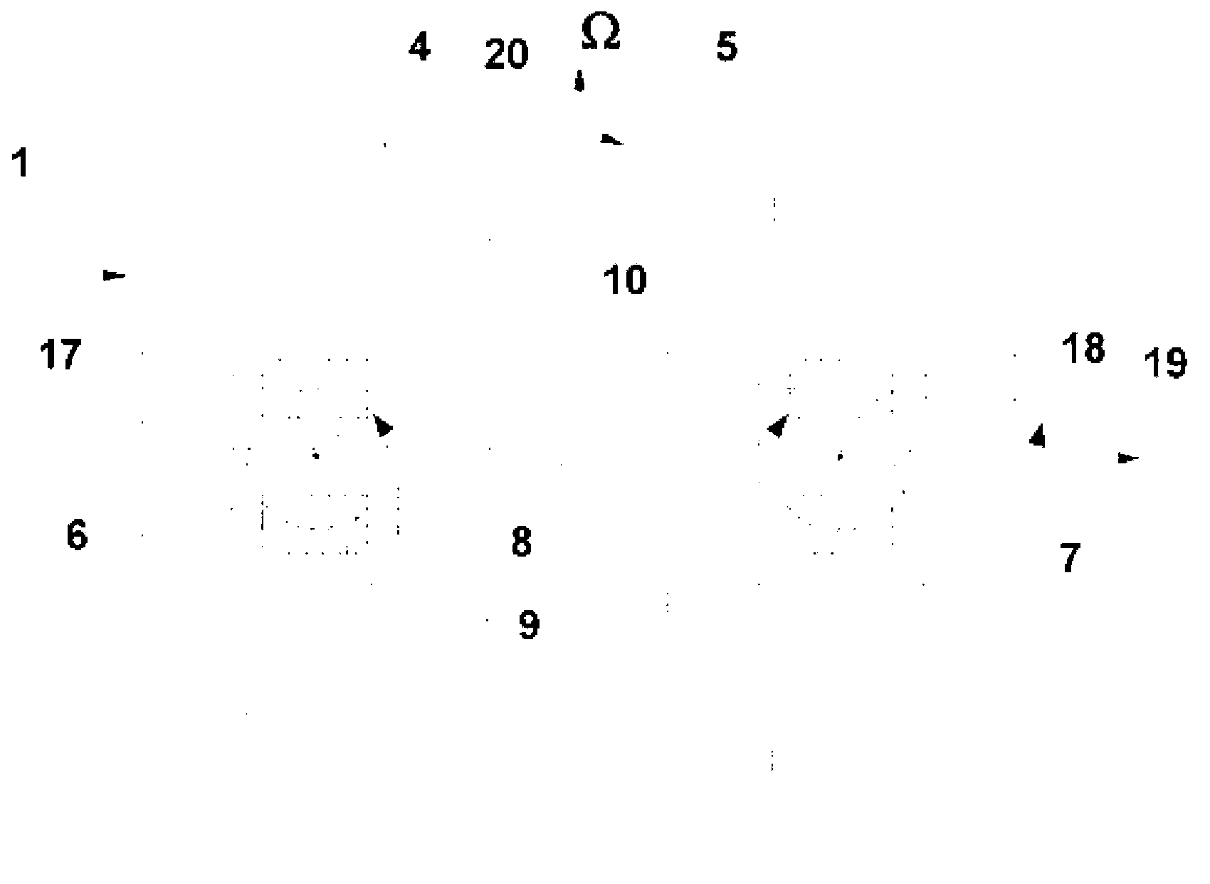
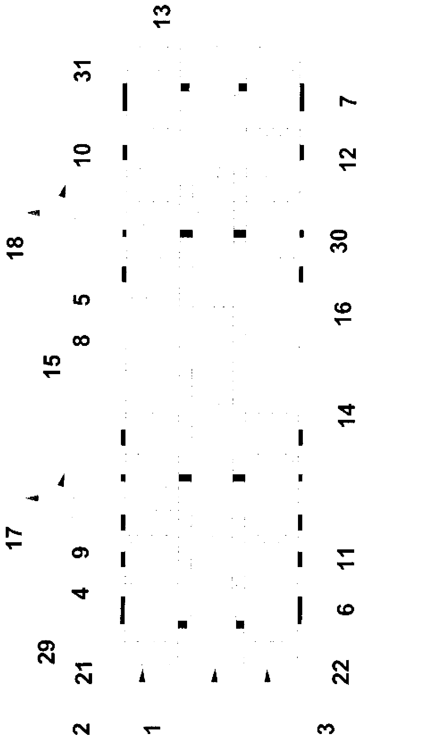
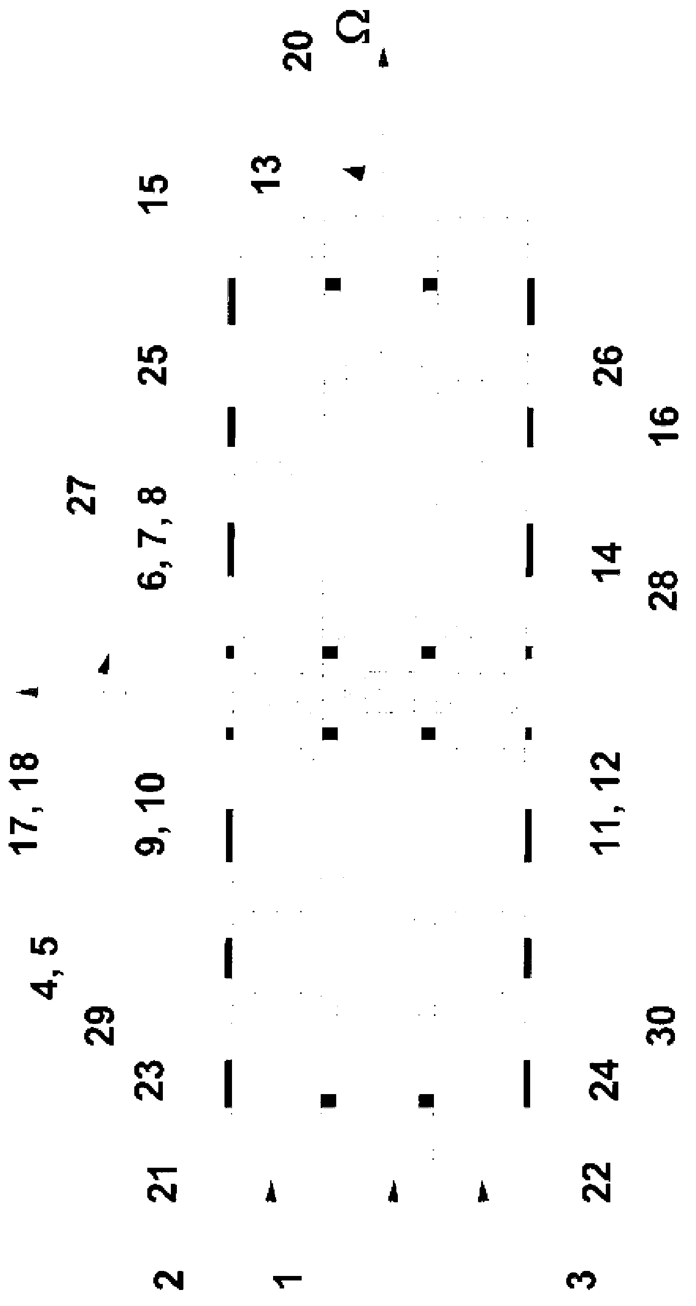
[0047] refer to figure 1 , the angular rate sensor according to the present invention comprises two sensitive masses 4, 5 connected by support beams 6, 7, 8, preferably the above two sensitive masses are identical. The beams and blocks are of substantially equal thickness and are preferably fabricated by high aspect ratio micromachining in a single crystal silicon substrate 1 . The geometry of the beams 6 , 7 , 8 is chosen in this example such that the beams tend to bend in a direction substantially parallel to the plane of the substrate 1 .

[0048] The blocks 4, 5 are connected to two support beams 6, 7, which act as drive beams. These drive beams 6, 7 are in turn connected to the two composite wafers 2 via at least two bases 9, 10, 11, 12 located in the center of the silicon substrate 1 and on the front and rear surfaces of the silicon substrate 1 , 3. The two blocks 4 , 5 are connected to each other by means of a curved spring 8 located in the center for mechanically sy...


PUM


Abstract

A micro-electromechanical system (MEMS) structure for an angular rate sensor, the structure being positioned between first and second silicon-insulator composite wafers formed of a plurality of structured silicon parts, electrically isolated from each other by an insulator material, the structure comprising: a mono-crystalline silicon substrate structured to form a sensing system and a frame, the sensing system being completely de-coupled from and surrounded by the frame, which is positioned between engaging surfaces of the first and second composite wafers such that the sensing system is hermetically sealed within a cavity defined by the first and second composite wafers and the frame, the sensing system including: two seismic masses having front and back surfaces; two driving beams, each having a first end attached to a seismic mass and a second end attached to the first and second composite wafers by means of fixed pedestals provided on the silicon substrate; and a bending spring arranged to directly connect between, and synchronise a primary motion of, the two seismic masses, each of the seismic masses being arranged to have a first degree of rotational freedom about an axis that is substantially perpendicular to the plane of the silicon substrate, and the seismic masses and driving beams being arranged to have a second degree of rotational freedom about an axis substantially coincident with the longitudinal axis of the driving beams; means for generating and detecting the primary motion consisting of a primary oscillation of the two seismic masses, in opposing phases, in the first degree of rotational freedom; and means of detecting a secondary motion consisting of a secondary oscillation of the two seismic masses, in opposing phases, in the second degree of rotational freedom, the means of generating and detecting the primary motion and the means of detecting a secondary motion being provided on both the front and back surfaces of each of the first and second seismic masses, wherein the sensing system is arranged such that, when the device is subjected to an angular velocity around a third axis that is substantially in the plane of the silicon substrate and perpendicular to the longitudinal axis of the beams, a Coriolis force arises which causes the secondary oscillation of the seismic masses.

Description

technical field [0001] The invention relates to a device for measuring angular velocity. More specifically, the present invention relates to a fully symmetric microelectromechanical system (MEMS) structure for an angular rate sensor with a double-sided implementation to provide high precision and stability. Background technique [0002] There is a considerable need for high precision and high stability angular rate sensors for use in various electronic measurement systems. Existing angular rate sensors include vibratory angular rate meters or gyroscopes (gyros), which use vibrating members such as tuning forks, and are constructed and tested with metals, quartz, and silicon. Quartz- and silicon-based gyroscopes are preferred over metal-based gyroscopes because they can be miniaturized and can be manufactured relatively cheaply by mass manufacturing in large production runs. [0003] A tuning fork type gyroscope requires an arrangement with at least two orthogonal degrees o...

Claims


Application Information

Patent Timeline
IPC IPC(8): G01C19/5712
CPCG01C19/5712
Inventor 佐蒙德·基特尔斯兰德丹尼尔·勒珀达图西塞尔·雅各布森
Owner 森松诺尔公司
Why Eureka
Try Eureka