Precise U-shaped bending die for magnesium alloy sectional materials

A technology of precision molds and magnesium alloys, applied in the direction of forming tools, manufacturing tools, metal processing equipment, etc., can solve the problems of reducing the stress of profiles, deformation and fracture of magnesium alloy profiles, and collapse of bending parts, so as to solve the problems of magnesium alloy deformation and fracture, profile Improve the spacing accuracy and ensure the effect of the internal organization structure

Active Publication Date: 2013-03-06
山西东银实业有限公司
View PDF8 Cites 8 Cited by
  • Summary
  • Abstract
  • Description
  • Claims
  • Application Information

AI Technical Summary

Problems solved by technology

[0005] Traditional U-shaped bending dies can no longer meet the increasingly high precision requirements of products (see figure 1 , figure 2 )
First of all, the center of the double arc of the traditional U-shaped bending die is a fixed distance, there is no adjustment margin, and it cannot be well adapted to the variable elasticity of the magnesium alloy material. The distance between the columns on both sides of the formed profile cannot be guaranteed. The traditional The yield of U-shaped bending die is less than 30%, and the loss and waste are serious
The second point is that the traditional U-shaped bending die has no guide wheels to reduce the stress of the profile, and the bent part after forming will collapse, and the product is not beautiful
The third point is that the traditional U-shaped bending die is under hard pressure, and the deformation and fracture of the magnesium alloy profile is serious.

Method used


Image

  • Precise U-shaped bending die for magnesium alloy sectional materials
  • Precise U-shaped bending die for magnesium alloy sectional materials
  • Precise U-shaped bending die for magnesium alloy sectional materials

Examples


Embodiment

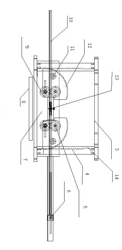
[0024] Example: figure 2 As shown, the present embodiment includes an upper mold frame and a lower formwork, and the upper mold frame is composed of an upper beam plate 3, a lower beam square iron 16 and two refined racks 4 to form a rectangular frame, wherein the upper beam plate 3 is located at the lower beam square iron 16 Above, the upper beam plate 3 is parallel to the lower beam square iron 16 and is horizontally arranged, and the two precision racks 4 are perpendicular to the upper beam plate 3 and the lower beam square iron 16 and are arranged on the upper beam plate 3 and the lower beam square iron 16. At both ends, two precision racks 4 are fixedly connected to the upper beam plate 3 and the lower beam square iron 16 to form a rectangular frame; a limit plate 14 is set behind the precision rack 4, and the rotating toothed plate 12 meshes with the precision rack 4 , the limit plate 14 is used to limit the rotation of the toothed disc 12, which can prevent the toothed...


PUM


Abstract

A precise U-shaped bending die for magnesium alloy sectional materials is mainly used for processing the magnesium alloy sectional materials. The die comprises an upper die frame and a lower die plate and is characterized in that the rectangular upper die frame consists of an upper crossbeam plate, a lower crossbeam steel pad and two precisely feeding racks, wherein the upper crossbeam plate and the lower crossbeam steel pad are horizontally arranged, the precisely feeding racks are vertically arranged as vertical sides, and the precisely feeding racks are connected to the upper crossbeam plate and the lower crossbeam steel pad; retaining plates are embedded on the outer sides of the precisely feeding racks, grooves are formed between the precisely feeding racks and the retaining plates, and rotating gear discs can slide in the grooves and are meshed with the precisely feeding racks; and two adjustable support wheels, the rotating gear discs and a retainer are arranged on the lower die plate, and a guide wheel and a molding wheel are arranged on each rotating gear disc. The deformation and breakage problems of magnesium alloy are basically solved. Through the fine adjustment of a wheel gap, the gap accuracy of the sectional materials is increased by 50%, and the defective rate is reduced by 80%.

Description

technical field [0001] The invention is mainly used for processing magnesium alloy profiles, and in particular relates to a U-shaped bending precision mold for magnesium alloy profiles. Background technique [0002] Profile processing products can be seen everywhere in our daily life. Bicycles, car seats, baby carriages, shopping carts, clothes hangers, construction site trolleys, wheelchairs for the disabled, walkers, etc. we use are all processed from profiles. Magnesium alloy Substituting aluminum alloys to make bicycles and other products is being promoted and popularized. [0003] The current price of magnesium alloy is only slightly higher than that of aluminum alloy in terms of weight, and its specific gravity is two-thirds of that of aluminum alloy, so its price is slightly lower than that of aluminum alloy in terms of volume. And magnesium alloy is the most widely used alloy in contemporary industrial engineering, with the lightest weight, higher specific strength ...

Claims


Application Information

Patent Timeline
Patent Type & Authority Applications(China)
IPC IPC(8): B21D37/10B21D7/08
Inventor 李志国王枫周贵平赵志龙
Owner 山西东银实业有限公司
Why Eureka
Try Eureka