Mechanism for changing conduction direction of ultrasonic wave

A technology of transmission direction and ultrasonic wave, applied in the field of mechanisms that change the transmission direction of ultrasonic waves, can solve problems such as complex structure, and achieve the effects of simple device structure, reduced distance, and enhanced hardness

Inactive Publication Date: 2013-03-06
韩连江
View PDF5 Cites 2 Cited by
  • Summary
  • Abstract
  • Description
  • Claims
  • Application Information

AI Technical Summary

Problems solved by technology

The device uses a tilting table and a rotating table. When processing the microstructure surface of superhard mold materials such as ceramics, according to the structure of the surface to be processed, the grinding direction is parallel to the vibration direction by adjusting the rotating table and the tilting table. This adjustment The method is to achieve the purpose of changing the direction by adjusting the workpiece. The structure of this method is relatively complicated, and it can only be applied to the grinding device. If it is replaced with a different device, it cannot be realized.

Method used


Image

  • Mechanism for changing conduction direction of ultrasonic wave
  • Mechanism for changing conduction direction of ultrasonic wave

Examples


Embodiment 1

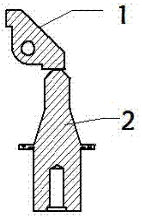
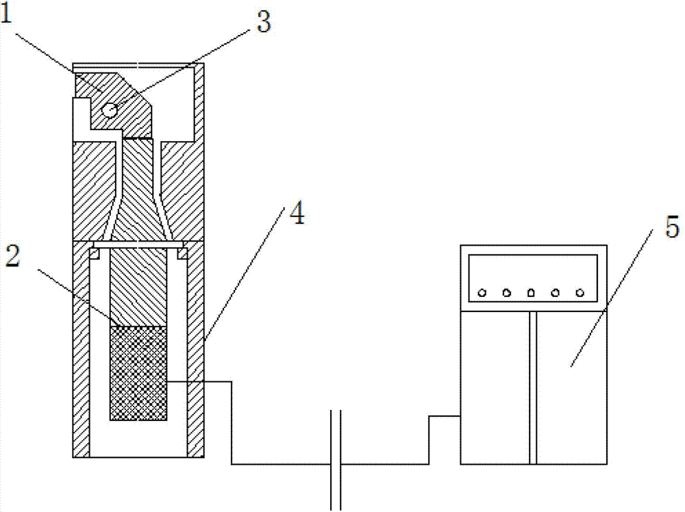
[0020] The present invention comprises a horn 2 and a rocker arm 1, one end of the rocker arm 1 is in contact with the head of the horn 2, the other end opposite to the end is perpendicular to the workpiece to be processed, and the center of the other end The angle between the line and the center line of the horn 2 is greater than 0 degrees. The rocker arm 1 is set on the housing 4 through the rocker shaft 3, the horn 2 is connected with the transducer, the rocker arm 1, the horn 2 and the transducer are all set in the housing 4, and the control box 5 is connected through the wire It is connected with the transducer in the shell 4. The rocker arm 1 can also be arranged outside the casing 4 .

[0021] One or both ends of the rocker arm 1 are ball joint structures. The original output amplitude of the ultrasonic wave can be adjusted by the length of the two ends of the rocker arm 1 using the lever principle.

[0022] A through hole can be set on the rocker arm 1, and the rock...

Embodiment 2

[0025] Such as figure 1 As shown, the present invention includes a horn 2 and a rocker arm 1, one end of the rocker arm 1 is in contact with the head of the horn 2, the other end opposite to the end is perpendicular to the workpiece to be processed, and the other end The centerline of the horn is perpendicular to the centerline of the horn 1. The rocker arm 1 is set on the housing 4 through the pin shaft 3, the horn 2 is connected with the transducer, the rocker arm 1, the horn 2 and the transducer are all arranged in the housing 4, the control box 5 is connected with the The transducers in the casing 4 are connected. The rocker arm 1 can also be arranged outside the casing 4 .

[0026] One or both ends of the rocker arm 1 are ball joint structures. The original output amplitude of the ultrasonic wave can be adjusted by the length of the two ends of the rocker arm 1 using the lever principle.

[0027] A through hole can be set on the rocker arm 1, and the rocker arm 1 can...


PUM


Abstract

The invention particularly discloses a mechanism for changing the conduction direction of ultrasonic wave, which comprises an amplitude-change pole and a rocker arm, wherein one end of the rocker arm is contacted with the head of the amplitude-change pole, the other end which is opposite to the end of the rocker arm is perpendicular to a workpiece to be machined, and the inclined angle between the centre line of the other end of the rocker arm and the centre line of the amplitude-change pole is more than 0 degree. The mechanism has the beneficial effects that the ultrasonic wave direction of the original ultrasonic wave device which is perpendicular to the workpiece to be machined is converted by the device through the rocker arm, so that the ultrasonic wave device can be in parallel with the workpiece to be machined, and the distance among the machining device, equipment and the workpiece can be reduced. The machining space can be enlarged, the machining range can be increased, the surface roughness can be reduced, and the surface hardness of the workpiece can be enhanced.

Description

[0001] technical field [0002] The invention specifically relates to a mechanism for changing the transmission direction of ultrasonic waves. Background technique [0003] Most of the existing ultrasonic processing devices (including cleaning, detection, metal surface processing, ultrasonic welding, etc.) use the ultrasonic transmission direction to move vertically with the workpiece or medium, and first convert the power frequency AC power into ultrasonic with a certain power output. Frequency electric oscillation, the transducer converts ultrasonic frequency electric oscillation into ultrasonic mechanical vibration, through the horn, the tool fixed at the end of the horn is vibrated to produce ultrasonic vibration, forcing the abrasive suspension to continuously hit and polish at high speed to be processed The surface shapes the workpiece. [0004] In the patent CN (102152175 A), an ultrasonic vibration-assisted grinding device for precision machining of microstructure s...

Claims


Application Information

Patent Timeline
Patent Type & Authority Applications(China)
IPC IPC(8): B24B1/04
Inventor 韩欣蔚韩连江
Owner 韩连江
Why Eureka
Try Eureka