

Propelling trolley
A trolley and propulsion mechanism technology, which is applied in the erection/assembly of bridges, bridges, buildings, etc., can solve the problems of poor eccentric load bearing capacity, difficult operation, and unfavorable construction of mobile formwork bridge building machines, so as to avoid eccentric loads. Effect
- Summary
- Abstract
- Description
- Claims
- Application Information
AI Technical Summary
Problems solved by technology
Method used
Image

Examples
Embodiment Construction
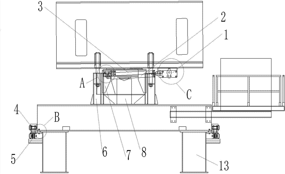
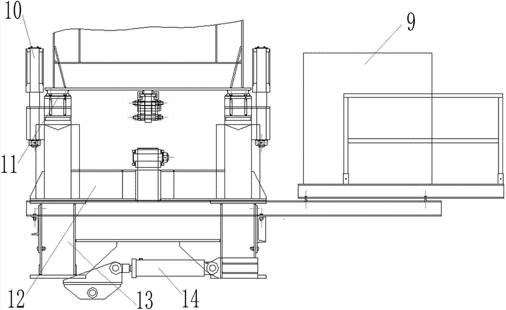
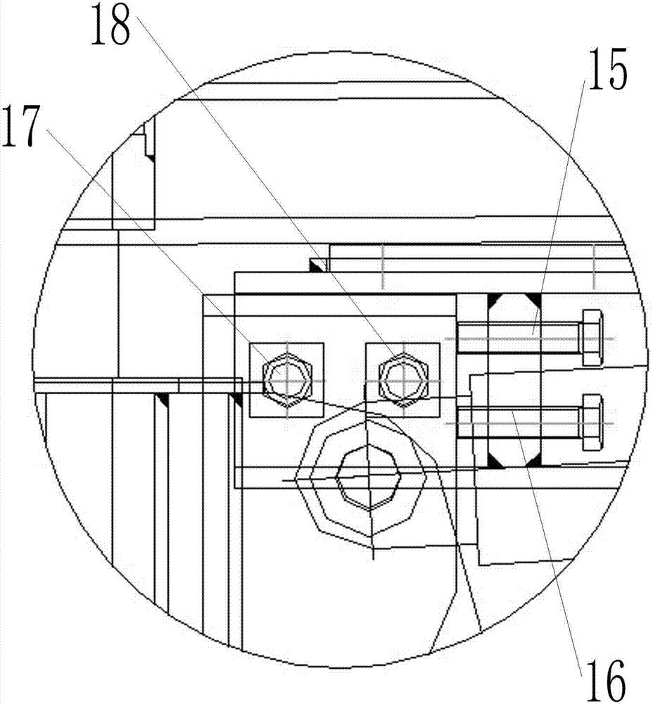
[0022] Attached below figure 1 to attach Figure 7 The present invention will be further described.
[0023] This propulsion trolley comprises trolley base 26, some connecting frame bodies 6 and hydraulic control system 9 installed on the top of trolley base 26, adjustment frame 7 on the up and down sliding installation and connecting frame body 6, vertically installed on the trolley base 26. Oil cylinder A, a traverse device that moves the trolley base 26 laterally relative to the corbel beam 13, a slope adjustment device arranged on the adjustment frame 7, and a longitudinal shift device installed on the trolley base 26 to move the main beam longitudinally, the oil cylinder A is connected to the hydraulic control system 9 . Under the action of the lateral movement device and the vertical movement device, the propulsion trolley can drive the main beam to move horizontally or vertically, and the oil cylinder A can push the adjustment frame upwards to realize the lifting of t...
PUM
 Abstract
Description
Claims
Application Information