Refrigerator compressor and lubricating-oil supplying device

A technology for refrigerator compressors and oil supply devices, which is applied to mechanical equipment, machines/engines, and liquid displacement machinery, etc. It can solve the problem of increasing the operating burden of the crankshaft and motor rotor 7, reducing the demand for lubricating oil, and reducing the work efficiency of the compressor and other problems, to achieve the effect of reducing the load of rotation, small oil supply and reducing energy consumption

Inactive Publication Date: 2013-03-06
WANBAO GROUP COMPRESSOR CO LTD
View PDF10 Cites 10 Cited by
  • Summary
  • Abstract
  • Description
  • Claims
  • Application Information

AI Technical Summary

Problems solved by technology

[0009] The oil supply method of the above structure has the advantages of large oil supply volume and wide oil supply range. However, with the improvement of the motor efficiency of the refrigerator compressor, the heat generated by the motor stator 71 and rotor 7 is getting smaller and smaller. For refrigerators with high energy efficiency The motor of the compressor basically does not generate heat during operation and does not need to cool down. The demand for lubricating oil jointly provided by the oil suction pipe 8 and the crankshaft is small. The operating burden of the rotor 7 increases the energy consumption of the motor and reduces the work efficiency of the compressor

Method used


Image

  • Refrigerator compressor and lubricating-oil supplying device
  • Refrigerator compressor and lubricating-oil supplying device
  • Refrigerator compressor and lubricating-oil supplying device

Examples


Embodiment Construction

[0030] The present invention will be further described below in conjunction with accompanying drawing.

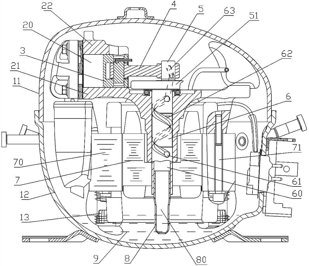
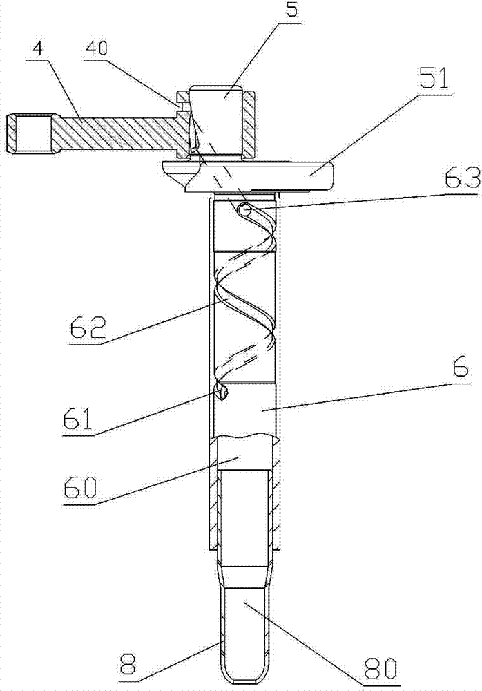
[0031] refer to figure 2 , image 3 , Figure 4 , a lubricating oil supply device for a refrigerator compressor, including a connecting rod 4, a crankshaft and an oil suction pipe 8;

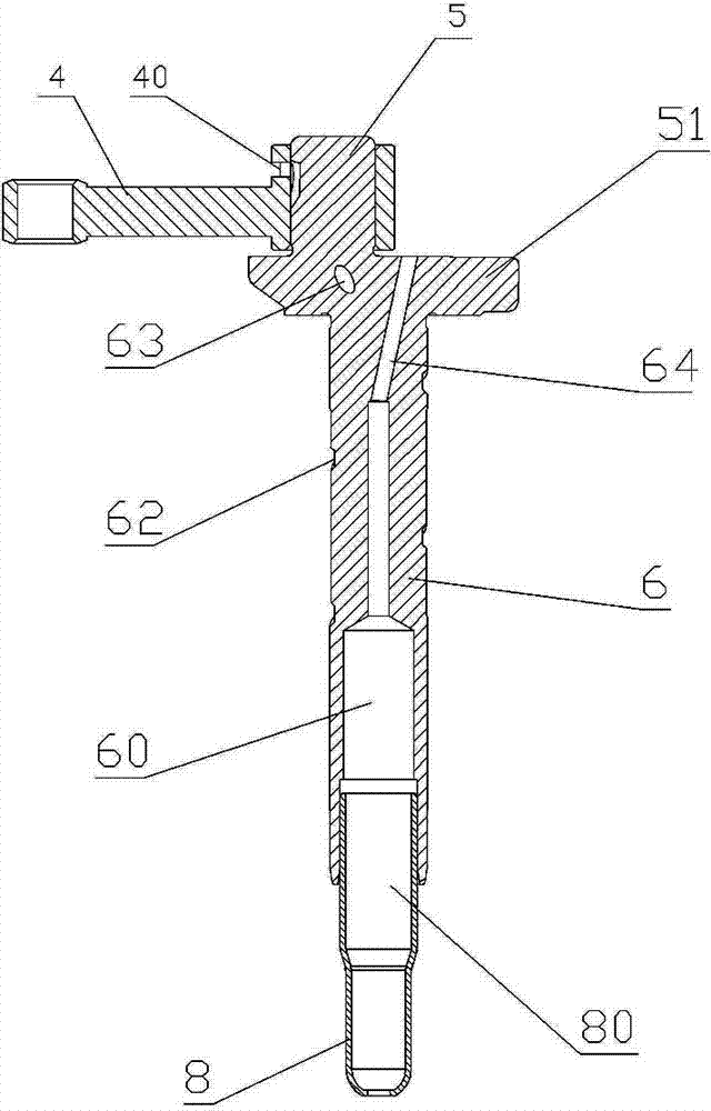
[0032] The crankshaft has a crankshaft part 5, a balance table part 51 and a main shaft part 6 which are sequentially connected in one piece. The middle part is located at the lower end of the outer oil groove 62 and has a middle oil hole 61, and the middle oil hole 61 communicates the outer oil groove 62 with the oil suction inner cavity 60;

[0033] The crankshaft part 5 has an upper oil hole 63 and an inner oil hole 64. The upper oil hole 63 extends through the crankshaft part 5 and the balance table part 51 to the main shaft part 6 and is connected to the upper end of the outer oil groove 62; the inner oil hole 64 passes through the balance The table portion 51 and the main shaft por...


PUM


Abstract

The invention relates to a refrigerator compressor and provides a lubricating-oil supplying device of the refrigerator compressor. The lubricating-oil supplying device comprises a connecting rod, a crank shaft and an oil suctioning pipe, wherein the crank shaft is provided with an oil supplying channel, an upper port of the oil supplying channel is positioned on the outer wall of the crank shaft part and a lower port of the oil supplying channel is positioned at the lower-tail end of a main shaft part; the two ends of the connecting rod are provided with a large ring-shaped column, a connecting rod and a small ring-shaped column; the large ring-shaped column of the connecting rod is provided with an exceeding part higher than the connecting rod; the exceeding part is provided with a horizontal oil supplying hole in the direction of the connecting rod; and the horizontal oil supplying hole corresponds the position of an upper oil hole of the crank shaft part. When the refrigerator compressor is in working, the lubricating oil reaches to the upper port through the oil supplying channel from an oil pool under the action of the centrifugal force; and when the large ring-shaped column of the connecting rod rotates to the horizontal oil supplying hole to be butted with the upper oil hole of the crank shaft, the lubricating oil penetrates through the horizontal oil supplying hole on the large ring-shaped column from the crank shaft and then is sprayed quickly and directionally towards the direction of the connecting rod so as to play a role of lubrication for the reciprocating movement of a piston. The invention has the following substantial characteristics and obvious progress that 1, the oil supplying amount of the lubricating oil supplying device is less, and good lubricating action can be achieved for relative movement of the piston, the connecting rod and the crank shaft; and 2, since the oil supplying amount of the lubricating oil supplying device is less, the rotating load of the crank shaft and a motor rotor is reduced, the energy consumption of the motor is reduced and the working efficiency of the compressor is increased.

Description

technical field [0001] The invention relates to a refrigerator compressor, in particular to a device for supplying lubricating oil to movable parts in the compressor. Background technique [0002] Refrigerator compressors are usually fully enclosed, and their structure refers to figure 1 , mainly includes a casing, a movement and a movement support structure 13, and the casing is formed by sealingly connecting an upper casing 11 and a lower casing 12. [0003] Movement comprises support 21, cylinder block 22, crankshaft, motor stator 70, motor rotor 7 and movement mounting bolt 71, and cylinder block 22 connects to support 21, and the cylinder 20 built-in piston 3 of cylinder block 22, motor stator 70 comprises stator The iron core and the stator winding wound on the stator iron core, the stator iron core is fixedly connected to the bottom of the bracket 21 through the core mounting bolt 71, and the middle part of the bracket 21 is provided with a shaft hole; [0004] The ...

Claims


Application Information

Patent Timeline
Patent Type & Authority Applications(China)
IPC IPC(8): F04B39/02
Inventor 吴小凌陈忠华陈会平吴丽华莫昭妮
Owner WANBAO GROUP COMPRESSOR CO LTD
Why Eureka
Try Eureka