Gauge for indirectly measuring inner hole spigot angle of differential bevel gear

A technology of inner hole spigot and bevel gear, which is applied in the field of indirect measurement of the bevel gear inner hole spigot angle inspection tool, can solve the problems of batch scrapping, low detection efficiency, and high requirements for inspection conditions, and achieves easy production, convenient operation, The effect of accurate data

Active Publication Date: 2013-03-06
JIANGSU PACIFIC PRECISION FORGING +1
View PDF6 Cites 4 Cited by
  • Summary
  • Abstract
  • Description
  • Claims
  • Application Information

AI Technical Summary

Problems solved by technology

The inner hole spigot in the differential bevel gear is the axial positioning reference of the installation position. The end face of the spigot in the inner hole has a certain angle, and the built-in spigot cannot be directly measured with conventional quantities and inspection tools.
Among modern testing equipment, profilers and three-dimensional coordinate measuring instruments can be used for precision measurement, but these precision instruments have high requirements for inspection conditions and low detection efficiency. They are only suitable for type inspection in the inspection room and cannot be used for on-site inspection in production
Due to the lack of necessary inspection tools in the workshop, the operators on the production line cannot find out the quality deviation in time, so they cannot take corrective measures in time, and batch scrapping accidents are likely to occur, resulting in economic losses

Method used


Image

  • Gauge for indirectly measuring inner hole spigot angle of differential bevel gear

Examples


Embodiment Construction

[0012] The present invention will be further described below according to the accompanying drawings and in conjunction with the embodiments.

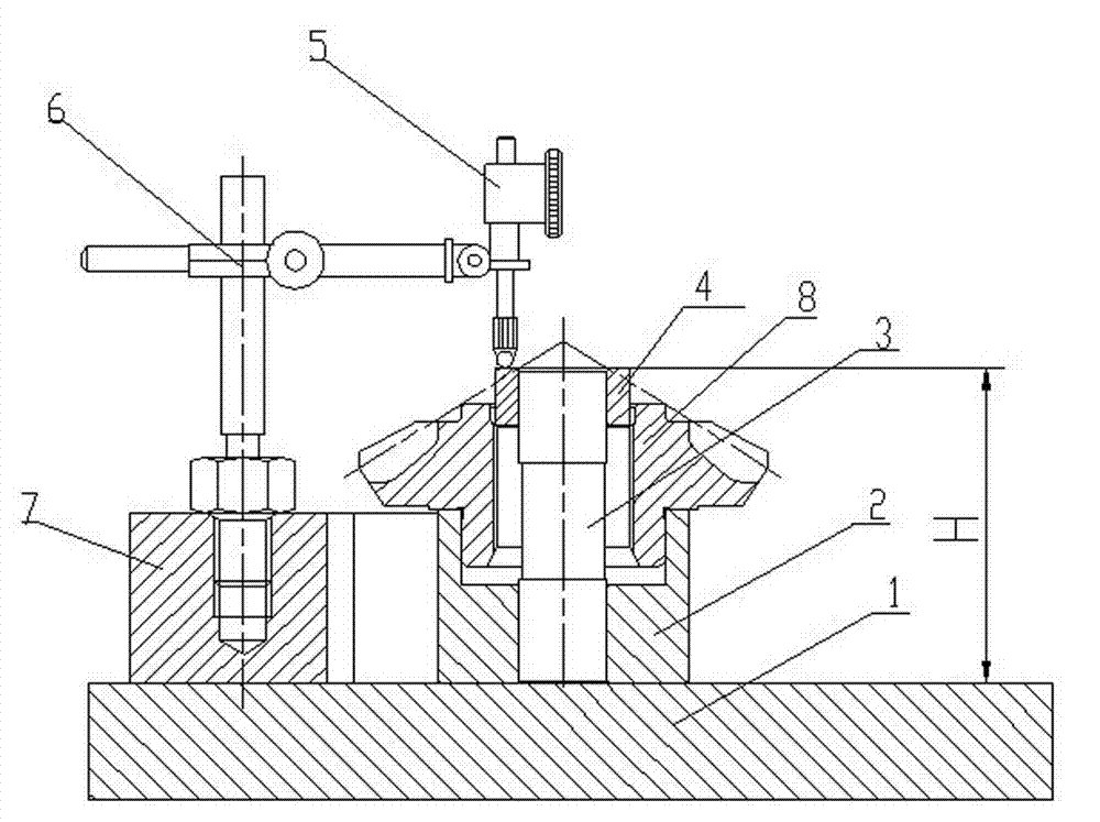
[0013] figure 1 The shown indirect measuring tool for differential bevel gear inner hole spigot angle includes a plate 1, a base 2, a mandrel 3, a positioning sleeve 4, a dial indicator 5, a gauge frame 6 and a V-shaped block 7. The flat plate 1 is a measurement reference plane in the present invention, the base 2 and the V-shaped block 7 are placed on the flat plate 1 respectively, and the V-shaped block 7 in a prone position is equipped with a positioning and measuring mechanism composed of a meter frame 6 and a dial indicator 5 . The base 2 is provided with an upward counterbore and a coaxial through hole, the upper end of the upper counterbore is parallel to the flat plate 1, the base 2 leans against the side of the positioning angle of the V-shaped block in a lying position, and is positioned and installed in the center of the thro...


PUM


Abstract

The invention discloses a gauge for indirectly measuring an inner hole spigot angle of a differential bevel gear. The gauge comprises a flat plate, a base, a core shaft, a locating sleeve, a dial indicator, a gauge stand and a V-shaped block, wherein the base and the V-shaped block are respectively arranged on the flat plate, and the horizontal V-shaped block is provided with a locating and measuring mechanism consisting of the gauge stand and the dial indicator; the base is provided with countersinks and a coaxial through hole, a workpiece is arranged in a countersink at the upper part of the base, and the core shaft is arranged in the through hole in a locating manner; an inner hole of the locating sleeve is in clearance fit with the core shaft, the locating sleeve respectively forms a small locating sleeve and a large locating sleeve according to two diameter values of a forming angle of a workpiece inner hole spigot, the small locating sleeve and the large locating sleeve are sequentially matched with the core shaft and are axially retained in the workpiece inner hole spigot, and the dial indicator of the locating and measuring mechanism respectively measures the heights from the upper end surfaces of the small locating sleeve and the large locating sleeve to the flat plate so that an angle error of the inner hole spigot is judged according to the height difference. The gauge disclosed by the invention has a pure mechanical structure and a low requirement on a measurement environment, is especially suitable for being configured in the production field, and is beneficial to immediate detection so as to reduce the economic loss caused by batch scrap.

Description

technical field [0001] The invention relates to a checking tool for measuring the height dimension, in particular, the invention relates to a checking tool for indirectly measuring the angle of the bevel gear inner hole spigot. Background technique [0002] The differential is an important part of the rear axle of the car and belongs to the precision transmission mechanism. Bevel gear transmission is a kind of angular transmission with a cantilever support structure, and its axial positioning accuracy determines the meshing quality of the matching bevel gear. The inner hole spigot in the differential bevel gear is the axial positioning reference of the installation position. The end face of the spigot in the inner hole has a certain angle, and the built-in spigot cannot be directly measured with conventional measuring tools. Among modern testing equipment, profilers and three-dimensional coordinate measuring instruments can be used for precision measurement, but these preci...

Claims


Application Information

Patent Timeline
Patent Type & Authority Applications(China)
IPC IPC(8): G01B5/24
Inventor 徐爱国赵红军朱正斌
Owner JIANGSU PACIFIC PRECISION FORGING
Why Eureka
Try Eureka