LED visible light communication system and light receiving antenna

A light-receiving antenna and light technology, which is applied in optics, condenser mirrors, optical components, etc., can solve problems such as difficulty in reconciling detector sensitivity and response time, easy to be interfered by stray light, unfavorable weak light detection, etc., and achieve anti-interference effect Good, to avoid the impact of stray light on the detector, to achieve multi-functional effect

Inactive Publication Date: 2013-03-06
KUANG CHI INTELLIGENT PHOTONIC TECH
View PDF5 Cites 5 Cited by
  • Summary
  • Abstract
  • Description
  • Claims
  • Application Information

AI Technical Summary

Problems solved by technology

However, the above-mentioned existing light-receiving antenna has the following defects: (1), it is easily interfered by stray light, and the anti-interference effect is poor; (2), the light is affected by aberration after passing through the lens, which is not conducive to weak light detection; 3), it is difficult to reconcile the contradiction between detector sensitivity and response time

Method used


Image

  • LED visible light communication system and light receiving antenna
  • LED visible light communication system and light receiving antenna
  • LED visible light communication system and light receiving antenna

Examples


Embodiment Construction

[0019] The present invention will be further described below in conjunction with accompanying drawing and specific embodiment:

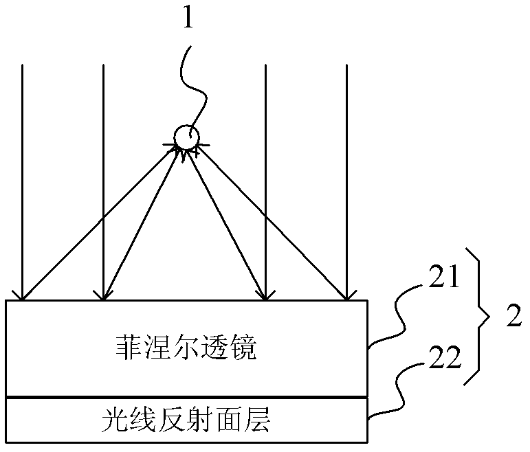
[0020] see figure 1 The light-receiving antenna of the present invention includes a photoelectric conversion device 1 and a light converging device 2, the light converging device 2 is provided with a Fresnel lens 21 and a light reflection surface layer 22, and the light reflection surface layer 22 is located on the Fresnel One side of the lens 21. The Fresnel lens 21 (Fresnel lens) is made of polyolefin material or glass, and is in the shape of a sheet. One side of the Fresnel lens 21 is engraved with concentric circles from small to large, and the other side is coated with a layer of the light reflection surface layer 22, that is, the light reflection surface layer 22 is coated on the surface of the Fresnel lens 21 , forming a reflective surface. The light reflecting surface layer 22 can be made of metal materials such as gold, silver, copper or ...


PUM


Abstract

The invention relates to an LED visible light communication system and a light receiving antenna. The light receiving antenna comprises a photoelectric conversion device and a light convergence device, wherein the photoelectric conversion device and a light source are arranged on the same side of the light convergence device; and the light convergence device is used for converging the incident light emitted by the light source on the photoelectric conversion device. The light receiving antenna has the beneficial effects that as the photoelectric conversion device and the light source are arranged on the same side of the light convergence device, the influence of stray light on a detector can be avoided and the anti-jamming effect is good; the aberration influence in the prior art can be avoided, thus being beneficial to detection of dim light; the inconsistency between the photoelectric conversion device and the response time thereof can be balanced; besides, the light source can be used for illumination, thus achieving multi-functionalization.

Description

technical field [0001] The invention relates to a light receiving device and its system, in particular to an LED visible light communication system and a light receiving antenna. Background technique [0002] The optical receiving antenna is one of the important components of the optical communication system, and it is usually used in occasions where radio frequency communication cannot provide services properly. Existing light-receiving antennas usually consist of a light converging device and a photodetector arranged at the focus of the light converging device. The light converging device is usually a convex lens or a Fresnel lens. For example, the Chinese patent with the patent application number CN200910235096.9 discloses a wireless communication optical receiving antenna. A Fresnel lens and a photodetector, the main Fresnel lens is a regular polygon; each of the secondary Fresnel lenses is bonded to the main Fresnel lens at a fixed angle, and the axis of the main Fresn...

Claims


Application Information

Patent Timeline
Patent Type & Authority Applications(China)
IPC IPC(8): G02B6/42G02B19/00G02B1/10H04B10/11
Inventor 刘若鹏栾琳刘京京马伟涛刘尧
Owner KUANG CHI INTELLIGENT PHOTONIC TECH
Why Eureka
Try Eureka