Programmable illuminator for photolithography system

一种光刻系统、照射器的技术,应用在激光器光学设备、微光刻曝光设备、图纹面的照相制版工艺等方向,能够解决不完备健全、光刻系统不良影响等问题

Inactive Publication Date: 2013-03-06
ULTRATECH INT INC
View PDF15 Cites 11 Cited by
  • Summary
  • Abstract
  • Description
  • Claims
  • Application Information

AI Technical Summary

Problems solved by technology

However, this mechanical solution is not robust and may fail, adversely affecting the MTBF of the lithography system

Method used


Image

  • Programmable illuminator for photolithography system
  • Programmable illuminator for photolithography system
  • Programmable illuminator for photolithography system

Examples


Embodiment Construction

[0037] In particular, the invention relates to a programmable illuminator for a photolithography system using a reticle or mask. An example of a lithographic system is described first, followed by a detailed description of an example of a programmable illuminator suitable for use within the example of the lithographic system.

[0038] Lithography system

[0039] An example embodiment of the present disclosure is a photolithography system using the programmable illuminator of the present disclosure. Examples of photolithographic systems in which the programmable illuminator disclosed herein are useful are described in US Patent Nos. 7,177,099, 7,148,953, 7,116,496, 6,863,403, 6,813,098, 6,381,077, and 5,410,434, all of which are incorporated by reference.

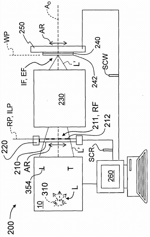
[0040] Please refer to figure 1 , is a schematic diagram of a photolithography system 200 suitable for the programmable illuminator disclosed in the present invention. The photolithography system 200 is along the optical ax...


PUM


Abstract

A programmable illuminator for a photolithography system includes a light source, a first optical system having a light uniformizing element, a programmable micro-mirror device, and a second optical system that forms an illumination field that illuminates a reticle. The programmable micro-mirror device can be configured to perform shutter and edge-exposure-blocking functions that have previously required relatively large mechanical devices. Methods of improving illumination field uniformity using the programmable illuminator are also disclosed.

Description

technical field [0001] The invention relates to a programmable illuminator used in a photolithographic system and a method for improving the uniformity of the irradiation field by the programmable illuminator. Background technique [0002] A photolithography system has its basic components, including an illuminator with a light source, a patterned reticle, a projection lens, and a light-sensitive (eg, photoresist-coated) wafer. The illuminator irradiates the reticle with light from the light source. The light is transmitted or reflected by the reticle, and then imaged on the photosensitive chip by the projection lens. After the photosensitive wafer is processed, a pattern is formed on the photosensitive wafer. Using many different reticles, the photolithographic exposure process and post-exposure process are repeated to form the semiconductor structures defining the integrated circuits on the wafer. [0003] A photolithography system needs to deliver a precise amount of e...

Claims


Application Information

Patent Timeline
Patent Type & Authority Applications(China)
IPC IPC(8): G03F7/20G02B26/10
CPCG03F7/70066G03F7/70558G03F7/20G02B26/0833H01S3/005
Inventor B・兹拉塔诺夫A・M・霍利鲁克
Owner ULTRATECH INT INC
Why Eureka
Try Eureka