
Non-contact power supply system for active current/voltage mutual inductor

A technology of voltage transformer and power supply system, which is applied in the direction of inductors, electromagnetic wave systems, transformers, etc., and can solve the problems of low conversion efficiency of solar cells

Active Publication Date: 2013-03-06
ELECTRIC POWER RESEARCH INSTITUTE, CHINA SOUTHERN POWER GRID CO LTD +1
View PDF5 Cites 2 Cited by
  • Summary
  • Abstract
  • Description
  • Claims
  • Application Information

AI Technical Summary

Problems solved by technology

This method has the advantages of low cost and easy implementation, but it is also susceptible to environmental factors such as light, dust accumulation, and battery aging, and the conversion efficiency of solar cells is low.

Method used


Image

  • Non-contact power supply system for active current/voltage mutual inductor

Examples


Embodiment Construction

[0017] The implementation of the present invention will be further described below in conjunction with the accompanying drawings, but the implementation and protection scope of the present invention are not limited thereto.

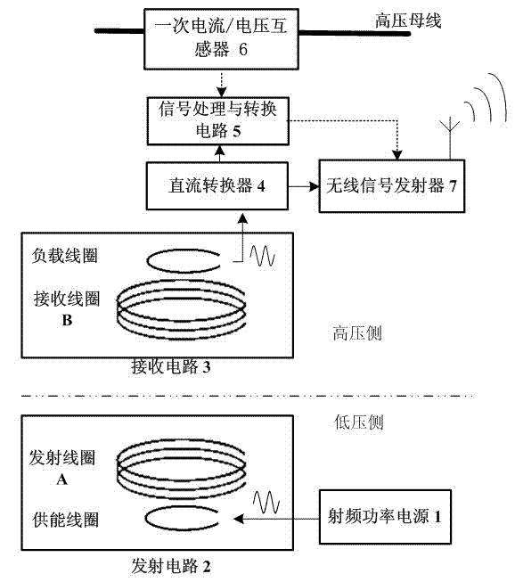
[0018] Such as figure 1 , a non-contact power supply system for active current / voltage transformers, which includes a radio frequency power supply 1, a transmitting circuit 2, a receiving circuit 3, a DC conversion circuit 4, a signal processing and conversion circuit 5, and a primary current / voltage transformer 6 and a wireless signal transmitter 7, wherein the radio frequency power supply 1 is directly connected to the transmitting circuit 2, the receiving circuit 3 is directly connected to the DC conversion circuit 4, and the DC conversion circuit 4 is connected to the signal processing and conversion circuit 5 and the wireless signal transmitter 7 , the signal processing and conversion circuit 5 is connected with the primary current / voltage transform...


PUM


Abstract

The invention provides a power supply system for providing non-contact power for an active current / voltage mutual inductor. The power supply system comprises a sinusoidal output radio frequency power supply, an emitting and receiving circuit, a direct current converter circuit, an active current / voltage mutual inductor and a wireless signal emitter, wherein the emitting circuit is arranged at the low-voltage side; a receiving circuit is arranged at the high-voltage side; an emitting coil A and a receiving coil B are multi-turn spiral coils of the same structure; and the natural frequency of the multi-turn spiral coils is kept to be consistent with the frequency of a radio frequency power supply. While working, the coils A and B are in a resonant state, electric energy is transmitted to the receiving coil B from the emitting coil A through electromagnetic fields; the coil B is completely coupled with a load coil, so that the load coil obtains electric energy, and then is rectified and filtered by the direct current converter circuit to provide direct current power to the active current / voltage mutual inductor at the high-voltage side and other signal processing and emitting devices. The non-contact power supply system disclosed by the invention achieves realizes complete isolation of a high-voltage circuit and a low-voltage circuit of the active current / voltage mutual inductor power supply system.

Description

technical field [0001] The invention relates to the power supply technology of voltage and current transformers, in particular to a non-contact power supply system based on resonant coupling type and active CT. [0002] Background technique [0003] The voltage and current transformers widely used in power station systems are traditionally of the electromagnetic induction type and have a transformer-like structure. With the increase of the power capacity transmitted by the power system, the voltage level is getting higher and higher, and various active current / voltage transformers gradually replace traditional transformers. Taking the hybrid optical fiber current transformer as an example, its working principle is: use the Rogowski coil on the high potential side to convert the bus current into a voltage signal. The (E / D) circuit converts this digital signal into an optical signal, and then sends it to the ground potential side through an optical fiber, and then converts i...

Claims


Application Information

Patent Timeline
Patent Type & Authority Applications(China)
IPC IPC(8): H02J17/00H01F38/14H02J50/12
Inventor 王学梅罗兵张波丘东元明哲
Owner ELECTRIC POWER RESEARCH INSTITUTE, CHINA SOUTHERN POWER GRID CO LTD
Learn More