Non-polarity electronic switch
An electronic switch, non-polarity technology, applied in the direction of electronic switches, electrical components, pulse technology, etc., can solve the problems of low reliability, high switching frequency, large relay volume, etc., and achieve the effect of simple and convenient installation and connection
- Summary
- Abstract
- Description
- Claims
- Application Information
AI Technical Summary
Problems solved by technology
Method used
Image

Examples
Embodiment 1
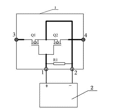
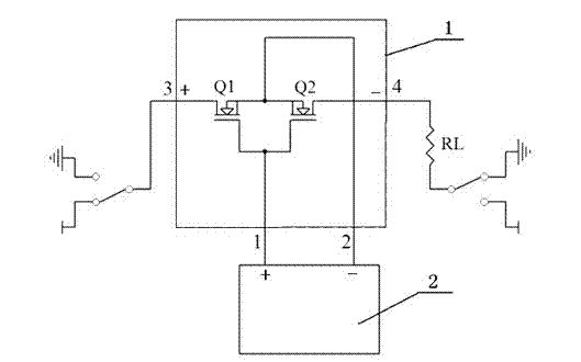
[0018] See figure 2 , a non-polar electronic switch, including a housing 1, the housing 1 is provided with a power circuit 3, 4 pins and a drive circuit 1, 2 pins, and the housing 1 is provided with two interconnected N-type MOSFET tubes Q1 and Q2, the gates of the two N-type MOSFET tubes Q1 and Q2 are connected to each other and then connected to pin 1 of the drive circuit, and the sources of the two N-type MOSFET tubes Q1 and Q2 are connected to each other and then connected to pin 2 of the drive circuit Connection, the drains of the two N-type MOSFET tubes Q1 and Q2 are respectively connected to pins 3 and 4 of the power circuit; pin 1 of the drive circuit is connected to the positive pole of MOSFET drive circuit 2, and pin 2 of the drive circuit is connected to the negative pole of MOSFET drive circuit 2 , the 3rd pin of the power supply circuit is connected to the positive pole (high end) of the power supply loop, and the 4th pin of the power supply loop is connected to ...
Embodiment 2
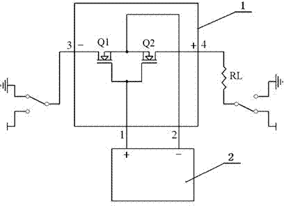
[0020] See image 3 , a non-polar electronic switch, including a housing 1, the housing 1 is provided with a power circuit 3, 4 pins and a drive circuit 1, 2 pins, and the housing 1 is provided with two interconnected N-type MOSFET tubes Q1 and Q2, the gates of the two N-type MOSFET tubes Q1 and Q2 are connected to each other and then connected to pin 1 of the drive circuit, and the sources of the two N-type MOSFET tubes Q1 and Q2 are connected to each other and then connected to pin 2 of the drive circuit Connection, the drains of the two N-type MOSFET tubes Q1 and Q2 are respectively connected to pins 3 and 4 of the power circuit; pin 1 of the drive circuit is connected to the positive pole of MOSFET drive circuit 2, and pin 2 of the drive circuit is connected to the negative pole of MOSFET drive circuit 2 , pin 3 of the power circuit is connected to the negative pole (ground terminal) of the power circuit, and pin 4 of the power circuit is connected to the positive pole (hi...
Embodiment 3
[0022] See Figure 4 , a non-polar electronic switch, including a housing 1, the housing 1 is provided with a power circuit 3, 4 pins and a drive circuit 1, 2 pins, and the housing 1 is provided with two interconnected P-type MOSFET tubes Q1 and Q2, the gates of the two P-type MOSFET tubes Q1 and Q2 are connected to each other and then connected to pin 1 of the drive circuit, and the sources of the two P-type MOSFET tubes Q1 and Q2 are connected to each other and then connected to pin 2 of the drive circuit Connection, the drains of the two P-type MOSFET tubes Q1 and Q2 are respectively connected to pins 3 and 4 of the power circuit; pin 1 of the drive circuit is connected to the negative pole of MOSFET drive circuit 2, and pin 2 of the drive circuit is connected to the positive pole of MOSFET drive circuit 2 , the 3rd pin of the power supply circuit is connected to the positive pole (high end) of the power supply loop, and the 4th pin of the power supply loop is connected to ...
PUM
 Abstract
Description
Claims
Application Information
PatSnap Eureka turns technology decisions into work you can execute. Powered by our Innovation Knowledge Graph, it runs expert workflows across engineering, life sciences, materials and intellectual property. Get your review-ready output in minutes.


