Recoil press

A press and pressure technology, applied in cranes, mechanical equipment, springs, etc., can solve the problems of increasing the length of the structure and increasing the weight, and achieve the effects of short assembly size, weight reduction, and easy replacement.

Inactive Publication Date: 2013-03-06
MONTANHYDRAULIK
View PDF10 Cites 2 Cited by
  • Summary
  • Abstract
  • Description
  • Claims
  • Application Information

AI Technical Summary

Problems solved by technology

This imposes an increased structural length compared to a hydraulic cylinder without an accumulator and thus increases the weight

Method used


Image

  • Recoil press
  • Recoil press
  • Recoil press

Examples


Embodiment Construction

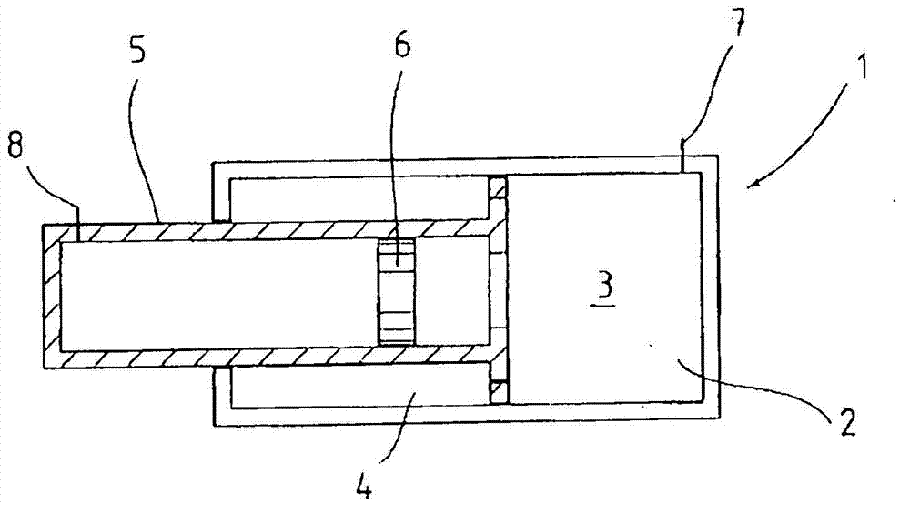
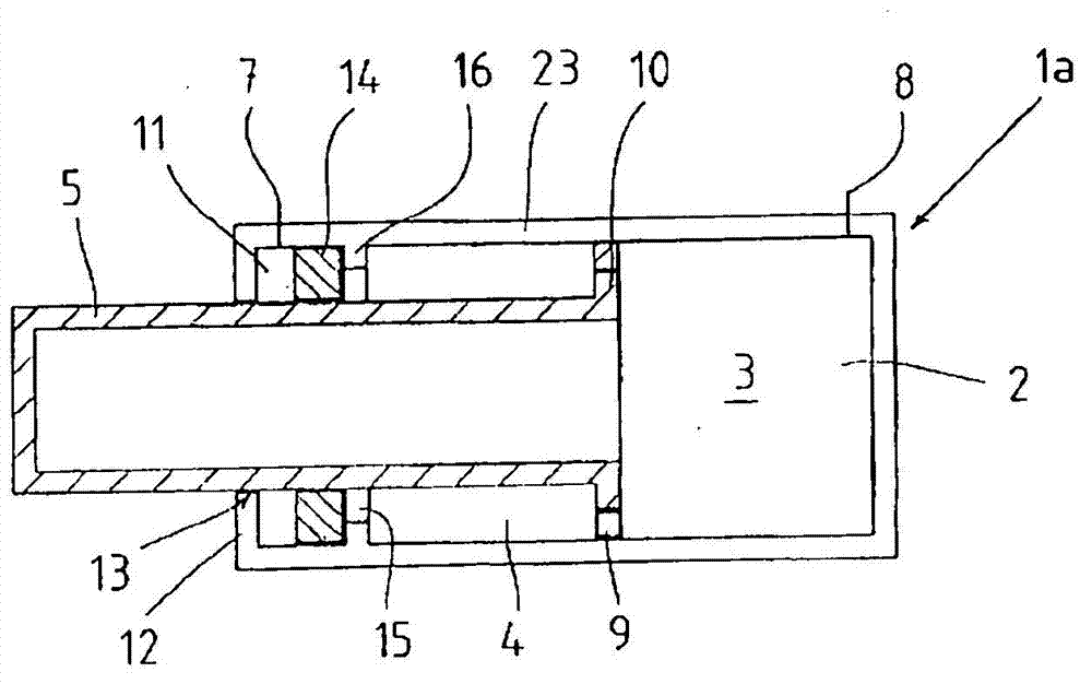
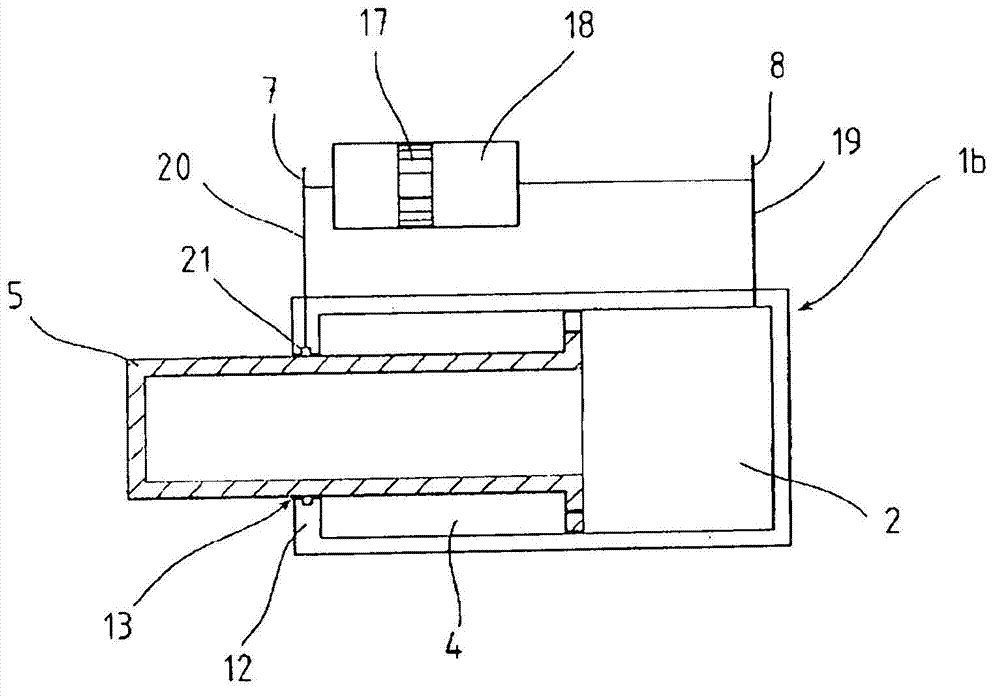
[0030] FIG. 1 shows the prior art, namely a recoil press 1 , in a greatly simplified view. The recoil press 1 has a cylinder cavity 2 filled with oil. The oil is present both in the bottom cavity 3 and in the annular cavity 4 , which is penetrated by the piston rod 5 .

[0031] The piston rod 5 is configured as a gas accumulator. The separating piston 6 in the piston rod 5 separates the gas, in particular N 2 , present in the piston rod 5 from the oil in other regions of the recoil press 1 .

[0032] The cylinder cavity 2 can be filled with oil via the connection 7 on the bottom cavity 3 . On the piston rod 5 there is a connection 8 via which the interior of the piston rod 5 can be filled with gas.

[0033] This arrangement has a relatively high weight due to the oil used and the isolation piston required to separate the oil from the gas. This solution has the following disadvantages: the volume of gas must be slightly larger than the volume of oil displaced in the recipro...


PUM


Abstract

The invention relates to a recoil press of a crane in the form of a gas cylinder, wherein, a piston rod engaged in a cylinder chamber of the gas cylinder is configured as a piston accumulator, and wherein the gas in the bottom space of the cylinder is communicated with the gas in the piston rod and the annular space surrounding the piston rod. A sealing arrangement in a rod guide of the cylinder seals the piston rod off from the cylinder. The sealing arrangement comprises a lubricant groove extending around the rod guide via which groove the exterior of the piston rod is lubricated. The lubricant is under the gas pressure prevailing in the cylinder with a pressure transmitting element being interposed.

Description

technical field [0001] The invention relates to a recoil press for a crane according to the features of the first claim 1 . The crane's jib lanyard reinforcement helps to increase loads. The lanyard reinforcement can be achieved by a rope or a tie rod and, for safe and reliable function, must be tracked and constantly tensioned when the jib moves or when the jib angle changes. An important element for this is the so-called recoil support. Background technique [0002] According to the prior art, a hydraulic cylinder is mounted on the recoil support, which applies a pressure from the jib to the recoil support in order to ensure a defined stress situation in the lanyard even when the jib is in a steep position. This hydraulic cylinder is called a recoil press and can be designed as a plunger cylinder or as a differential cylinder. In some cases, this hydraulic cylinder is not connected to the central hydraulic system. Oil exchange is achieved through an external pressure a...

Claims


Application Information

Patent Timeline
Patent Type & Authority Applications(China)
IPC IPC(8): B66C23/82B66C23/92F16F9/36
CPCB66C23/82F16F9/3278F16F9/365B66C23/92
Inventor C·施塔门
Owner MONTANHYDRAULIK
Why Eureka
Try Eureka