
Method for demagnetizing magnetic powder

A magnetic powder, demagnetization technology, applied in the direction of magnetic objects, electrical components, circuits, etc., can solve the problems of short circuit risk, poor conduction, and easy movement of conductive particles

Active Publication Date: 2013-03-06
DEXERIALS CORP
View PDF5 Cites 0 Cited by
  • Summary
  • Abstract
  • Description
  • Claims
  • Application Information

AI Technical Summary

Problems solved by technology

[0003] However, when a semiconductor chip is anisotropically conductively connected to a wiring board using an anisotropic conductive film using nickel-coated resin particles as conductive particles, the insulating adhesive component melts and flows during the anisotropic conductive connection. Therefore, the conductive particles also become easy to move, and as a result, there is a problem that magnetic conductive particles aggregate
Such agglomeration of the generated conductive particles leads to the localization of the conductive particles, which increases the risk of poor conduction or short circuit.

Method used


Image

  • Method for demagnetizing magnetic powder
  • Method for demagnetizing magnetic powder
  • Method for demagnetizing magnetic powder

Examples


Embodiment 1

[0050] Example 1 (demagnetization treatment by the second mode of the demagnetization method)

[0051] (Demagnetization treatment of conductive particles)

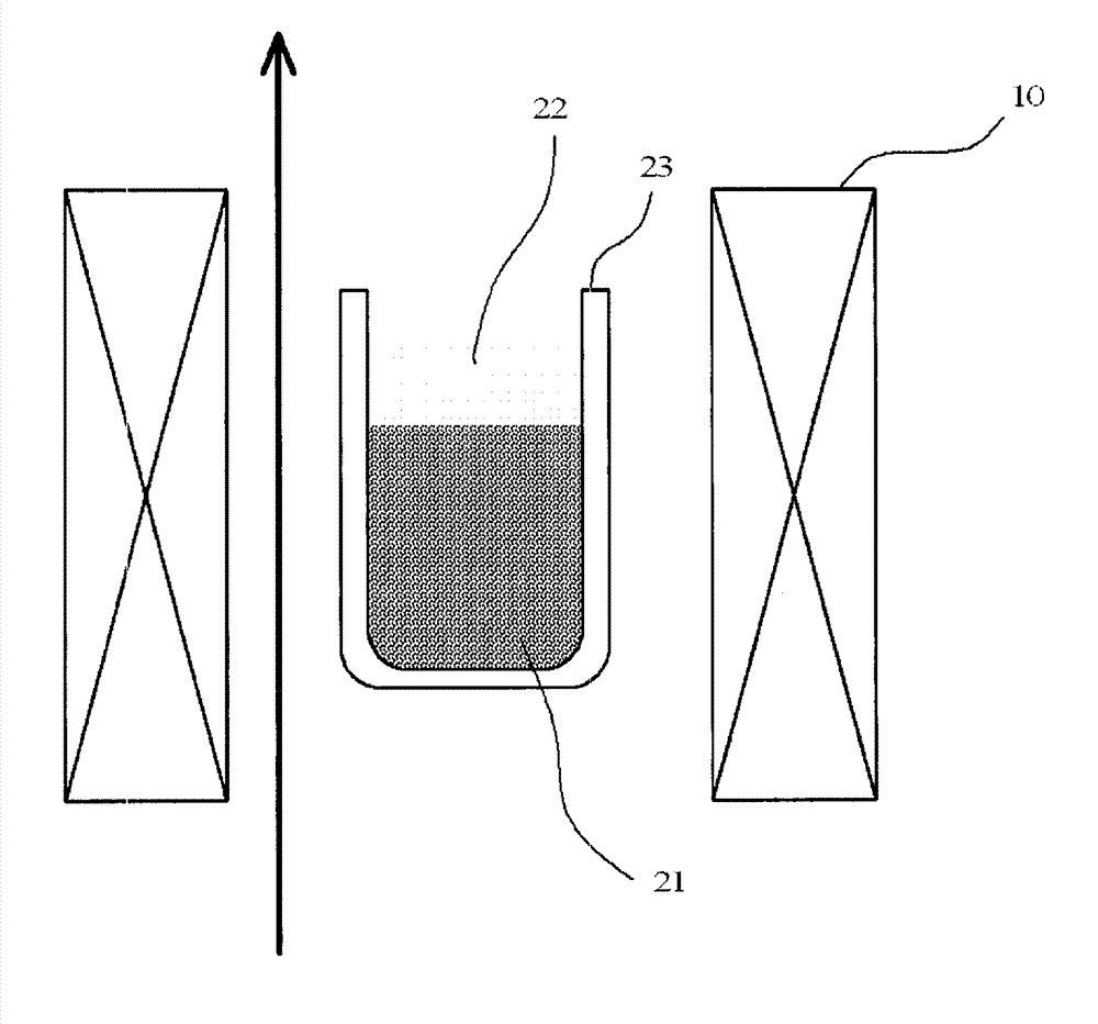
[0052] 100 g of nickel-coated resin particles with an average particle diameter of 3 to 4 μm, prepared as described later, were put into a solvent-resistant cylindrical container made of glass with a capacity of 900 ml and an opening inner diameter of 10 cm and a depth of 20 cm. Alkanes 500g, disperse and mix.

[0053] The cyclohexane mixture was cooled to -40°C to solidify. The glass container containing the solidified cyclohexane mixture was placed in a through-type demagnetization device (manufactured by Soni Chemicul & Informatics Co., Ltd.), and the demagnetization treatment was performed under the conditions shown in Table 1 and Table 2. After the demagnetization treatment, the temperature was returned to room temperature, and nickel-coated resin particles were obtained by filtration from cyclohexane, washed with h...

Embodiment 2

[0090] Example 2 (Demagnetization treatment by the first mode of the demagnetization method)

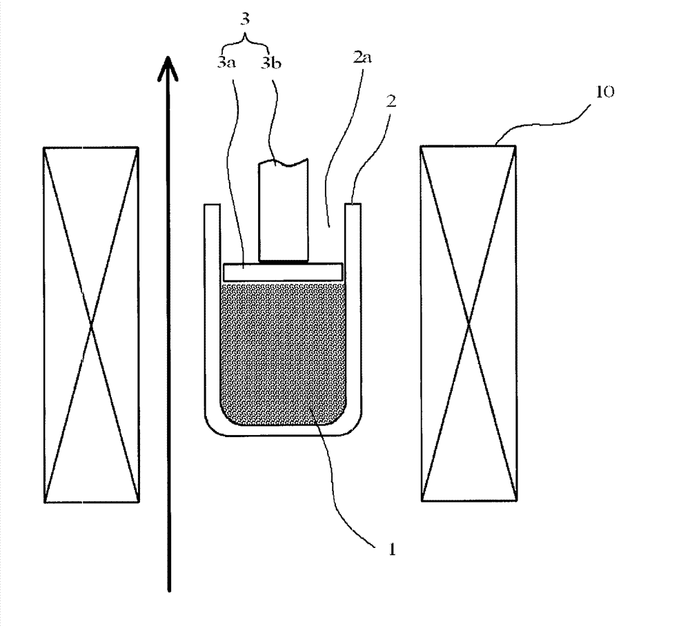
[0091] In a solvent-resistant cylindrical vessel made of glass with an opening inner diameter of 60 mm and a depth of 70 mm and a capacity of 100 ml, the same nickel-coated resin particles (demagnetized) with an average particle diameter of 3 to 4 μm as the particles prepared in Example 1 were placed. Untreated) 100g. The surface of the resin particle was located 20 mm away from the mouth. In addition, nickel contains 4 mass % of phosphorus atoms.

[0092] Next, a disk-shaped glass plate with a diameter of 60 mm and a thickness of 10 mm was placed on the surface of the resin particles from the opening, and it was pressed with a force of 500 N to detachably fix it. The glass container was placed in a through-type demagnetization device (manufactured by Soni Chemicul & Informatics Co., Ltd.), and demagnetized at room temperature with a magnetic field intensity of 400G and a demagneti...


PUM

PropertyMeasurementUnit
The average particle sizeaaaaaaaaaa
Connection resistance valueaaaaaaaaaa

Abstract

In the disclosed method for demagnetizing magnetic powder: the magnetic powder is placed in a container having an opening, a pressing means is inserted into the container from the opening thereof, the magnetic powder is pressed with the pressing means so that the magnetic powder is temporarily fixed inside the container, and then the magnetic powder is demagnetized; or the magnetic powder is placed in a liquid, the liquid is solidified so that the magnetic powder is temporarily fixed in the solid, and then the magnetic powder is demagnetized. In the latter case, first the magnetic powder is placed in the liquid, the liquid is then subjected to a bubble-removal process, and then the liquid is solidified. The liquid is solidified by cooling the liquid to a temperature equal to or below the freezing point thereof.

Description

technical field [0001] The invention relates to a demagnetization method of magnetic powder. Background technique [0002] The anisotropic conductive film is produced by dispersing conductive particles in an insulating adhesive and molding the obtained dispersion into a film. In this case, as the conductive particles, in accordance with the finer pitch of the wiring, particles with a smaller particle size are gradually used. In addition, it is desirable to use conductive particles that exhibit conductivity and deformability suitable for anisotropic conductive connection and obtain Relatively low-cost resin particles coated with a nickel plating film (hereinafter referred to as nickel-coated resin particles). [0003] However, when a semiconductor chip is anisotropically conductively connected to a wiring board using an anisotropic conductive film using nickel-coated resin particles as conductive particles, the insulating adhesive component melts and flows during the anisotr...

Claims


Application Information

Patent Timeline
IPC IPC(8): H01F13/00
CPCH01F13/006H01F13/00
Inventor 坂本淳
Owner DEXERIALS CORP
Learn More