Liquid crystal panel driving circuit, liquid crystal display device and driving method

A technology of liquid crystal panel and driving circuit, which is applied in the direction of digital output to display equipment, static indicator, cathode ray tube indicator, etc. Simplified design, simple and reliable results

Active Publication Date: 2013-03-13
SHENZHEN CHINA STAR OPTOELECTRONICS TECH CO LTD
View PDF4 Cites 12 Cited by
  • Summary
  • Abstract
  • Description
  • Claims
  • Application Information

AI Technical Summary

Problems solved by technology

However, in this solution, the left and right screens are often

Method used


Image

  • Liquid crystal panel driving circuit, liquid crystal display device and driving method
  • Liquid crystal panel driving circuit, liquid crystal display device and driving method
  • Liquid crystal panel driving circuit, liquid crystal display device and driving method

Examples


Embodiment Construction

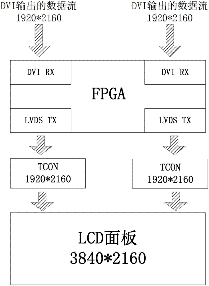
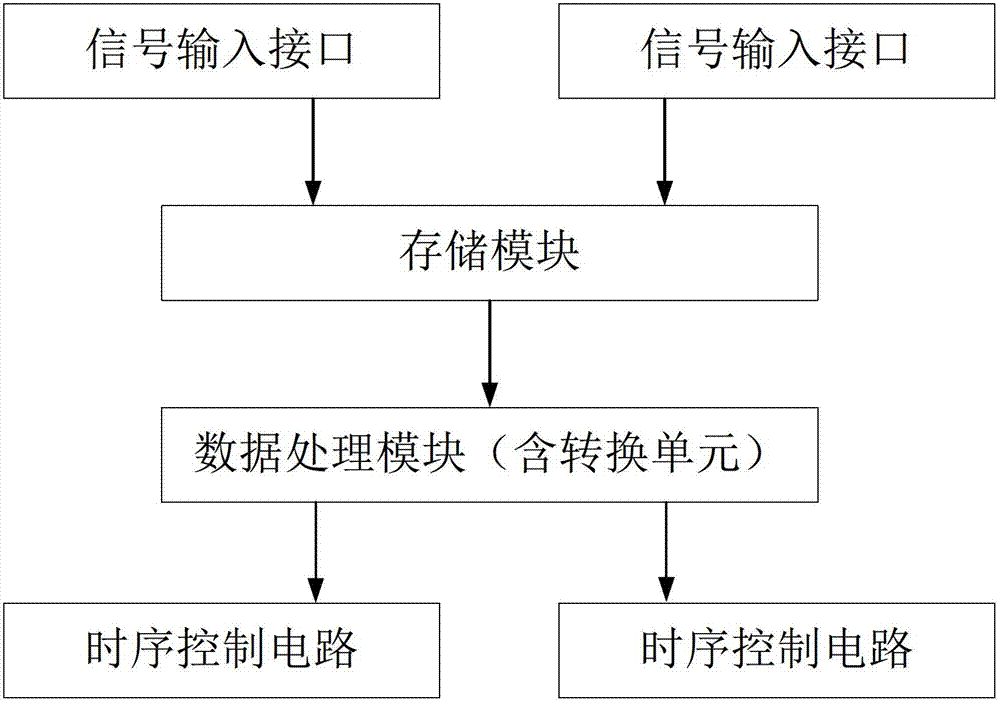
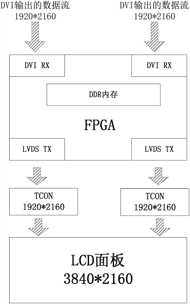
[0029] The invention discloses a liquid crystal display device, which comprises a driving circuit of a liquid crystal panel. Such as figure 2 As shown, the driving circuit of the liquid crystal panel includes at least two signal input interfaces and a timing control module, and the driving circuit also includes a storage module and a data processing module;

[0030] After the storage module receives the picture data of the same display picture of all signal input interfaces, the data processing module reads the picture data from the storage module and sends it to the timing control module, and the timing control module drives the liquid crystal panel.

[0031] The inventors found that due to the fact that the display card or other display devices have a certain time difference when receiving multiple input screen data, and the time difference is not fixed (one line of data or more), the left and right pictures are not synchronized, thus affecting the normal display of the pic...


PUM


Abstract

The invention discloses a liquid crystal panel driving circuit, a liquid crystal display device and a driving method. The liquid crystal panel driving circuit comprises at least two signal input interfaces, a time sequence control module, a storage module and a data processing module. When the storage module receives frame data of one same display frame of all the signal input interfaces, the data processing module reads the frame data from the storage module and transmits the frame data to the time sequence control module which then drives a liquid crystal panel. The liquid crystal panel driving circuit solves the problem in the prior art that frames are not synchronous, and can improve display quality.

Description

technical field [0001] The invention relates to the field of liquid crystal display, and more specifically, relates to a driving circuit of a liquid crystal panel, a liquid crystal display device and a driving method. Background technique [0002] Currently, conventional LCD TVs in the market have HDMI, DVI, Display Port, etc., but for ultra-high-definition LCD panels (LCD Panel) with a resolution of 3840X2160 and above, due to bandwidth limitations, a single input can currently support such a high resolution The interface only has 30Hz HDMI input signal, but the flicker is easy to be observed by the human eye. Therefore, the common architecture is dual signal input, such as figure 1 As shown, taking the DVI input as an example, the image signal is divided into 1 / 2, and then the two input signals are input from the DVI interface to the programmable logic array (FPGA), and the FPGA then combines the signals of the two interfaces. Combine the two 1 / 2 image signals, and then ...

Claims


Application Information

Patent Timeline
IPC IPC(8): G09G3/36
CPCG09G3/20G06F3/14G09G3/36G09G3/2096G09G5/005G09G5/006G09G5/12G09G2340/0407G09G2350/00G09G2352/00G09G2360/18G09G2370/12G09G2370/20
Inventor 谭小平秦杰辉张勇
Owner SHENZHEN CHINA STAR OPTOELECTRONICS TECH CO LTD
Why Eureka
Try Eureka