Dynamic separation material discharging type grinding machine

A technology for separating and grinding machines, applied in the field of grinding machines, can solve the problems of reduced grinding efficiency, large rotational power, and insufficient grinding precision, and achieve the effect of solving the inconvenience of cleaning and replacing separators, improving grinding efficiency, and improving grinding precision

Active Publication Date: 2013-03-20
PUHLER GUANGDONG SMART NANO TECH CO LTD
View PDF10 Cites 15 Cited by
  • Summary
  • Abstract
  • Description
  • Claims
  • Application Information

AI Technical Summary

Problems solved by technology

The grinding precision of this traditional grinding machine is not enough because only rod pins are installed on the rotor; also because the separator and the discharge chamber are statically fixed, it is easy to cause materials and grinding media to block the separator and reduce the grinding efficiency; also because the rotor Generally made of metal, its mass is relatively large, and the rotational power to be provided is relatively large, so the energy consumption is relatively high, and the shearing force generated is not enough at the same time

Method used


Image

  • Dynamic separation material discharging type grinding machine
  • Dynamic separation material discharging type grinding machine
  • Dynamic separation material discharging type grinding machine

Examples


Embodiment Construction

[0020] Below in conjunction with accompanying drawing, the present invention is described in further detail:

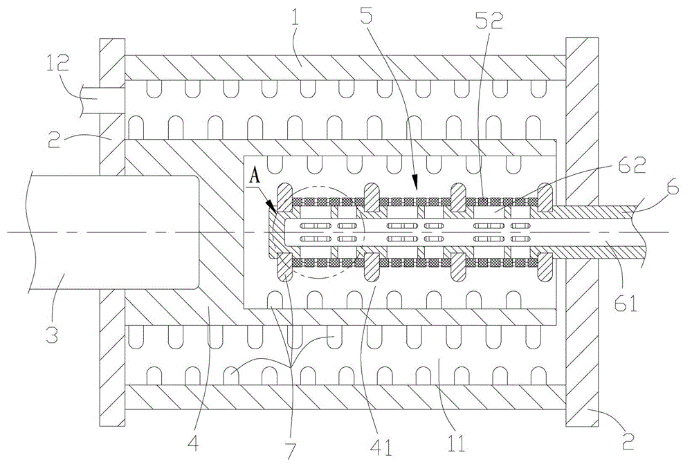
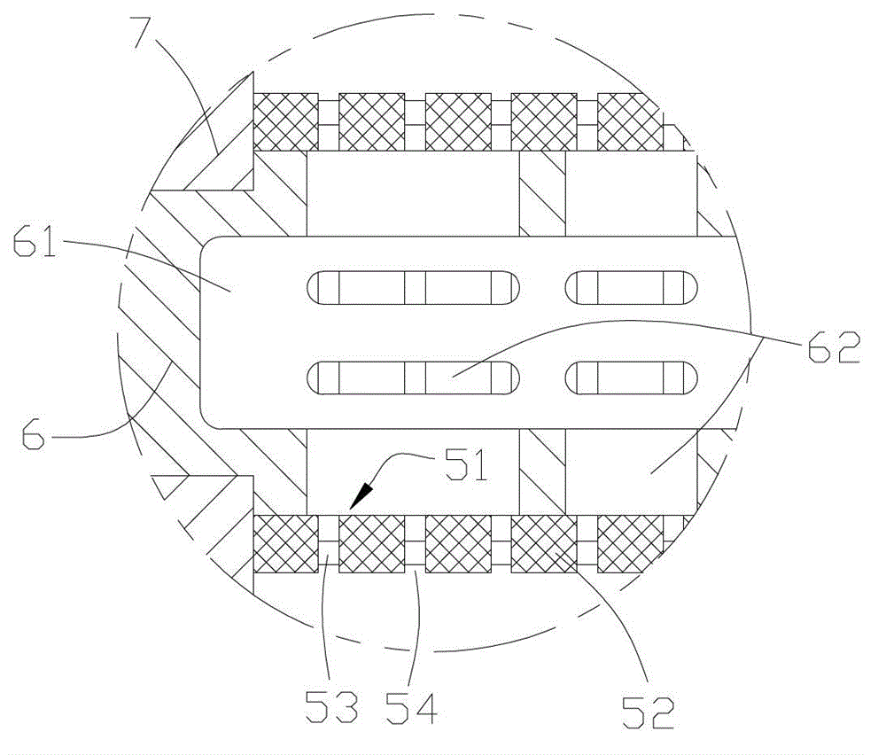
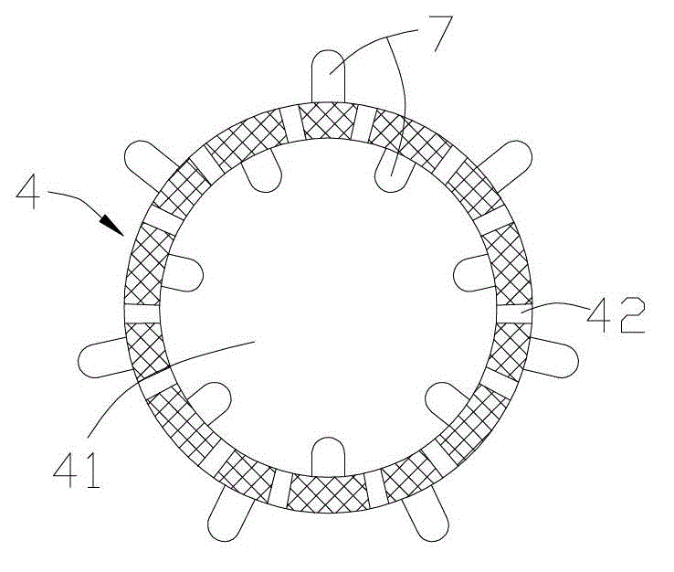
[0021] Such as figure 1 The grinding machine includes a grinding cylinder 1 with a grinding cavity 11 formed inside and a feeding cavity 12 communicating with the grinding cavity. The end cover extends into the grinding chamber, and one end of the grinding rotor 4 in the grinding chamber is installed on the main shaft and rotates with the main shaft; a separator 5 is arranged in the material chamber 41 formed at the other end of the grinding rotor, and a separator 5 is arranged on the rotor. The material hole 42 connected to the material cavity is driven by the motor to rotate and the discharge shaft 6 with the discharge cavity 61 formed inside extends into the material cavity from the other end cover, and the separator that rotates with it is installed on the discharge shaft , the separation chamber 51 of the separator communicates with the discharge chamber 61 of t...


PUM


Abstract

The invention relates to a dynamic separation material discharging type grinding machine, comprising a grinding cylinder which is internally molded with a grinding cavity, and a feeding cavity communicated with the grinding cavity, wherein the two ends of the grinding cavity are respectively sealed by end covers; a main shaft penetrates through one end cover to stretch into the grinding cavity; one end of a grinding rotor in the grinding cavity is mounted on the main shaft; a material discharging shaft stretches into a material cavity from the other end cover; the material discharging shaft is provided with a separator; and a separation cavity of the separator is communicated with a material discharging cavity of the material discharging shaft. Four layers of rod pins are formed at the inner and outer sides of a grinding rotor, in the grinding cylinder and on the material discharging shaft, so that grinding materials are sufficiently grinded and the grinding precision is improved; and the separator of the grinding machine is driven by the motor to rotate to form dynamic separation so that the materials has small possibility of blocking the separator.

Description

[0001] technical field [0002] The present invention relates to grinding machines. Background technique [0003] There are many types of grinding machines, including those used for ultra-fine grinding, such as: sand mill, bead mill, Raymond mill, pile mill, etc.; also include wet grinding machines, such as: ball mill, colloid mill machine, jet mill, ultrasonic mill, stirring mill, homogenizer, drum mill and similar grinding machines. At present, in large-scale industrial production, it is necessary to improve efficiency, shorten passing time, micronize and disperse grinding products, achieve narrow particle size distribution, make grinding machines easy to clean and replace products quickly, improve the versatility of low-viscosity products, and significantly The reduction of temperature rise during dispersion is a very important part of the mill and the main research direction. A traditional grinding machine generally includes a grinding cylinder with a grinding cavity f...

Claims


Application Information

Patent Timeline
Patent Type & Authority Applications(China)
IPC IPC(8): B02C17/16B02C17/20B02C23/10
Inventor 雷立猛
Owner PUHLER GUANGDONG SMART NANO TECH CO LTD
Why Eureka
Try Eureka