Separator for part surface treatment sand

A surface treatment and separator technology, applied in the field of surface treatment of parts, can solve the problems of incompleteness, low efficiency, slow speed, etc., and achieve the effect of saving labor, saving physical strength, and fast speed.

Inactive Publication Date: 2013-03-20
安徽朝阳车链有限公司
View PDF5 Cites 4 Cited by
  • Summary
  • Abstract
  • Description
  • Claims
  • Application Information

AI Technical Summary

Problems solved by technology

After the surface treatment, the parts are mixed with water and sand, and it is not easy to separate the parts from the sand. Some of the existing technologies use manual tools for separation, which wastes a lot of physical strength and labor, and the separation is not clean and thorough, and the speed slower, less efficient

Method used


Image

  • Separator for part surface treatment sand

Examples


Embodiment Construction

[0011] In order to make the technical means, creative features, objectives and effects achieved by the present invention easy to understand, the present invention will be further described below in conjunction with specific illustrations.

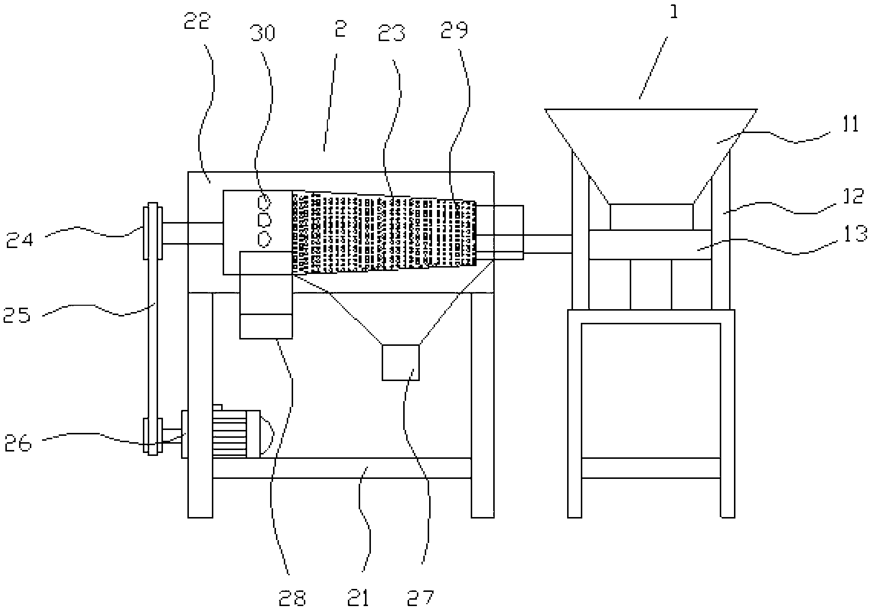
[0012] Such as figure 1 As shown, the parts surface treatment sand separator includes a feeding device 1, a separation device 2 arranged at the rear end of the feeding device 1; Feed pipe 13 below; Separator 2 comprises separation support 21 and is located at the box body 22 above separation support 21, is located at box body 22 internal separation cylinder 23, and the end of separation cylinder 23 is provided with pulley 24, and pulley 24 passes through The belt 25 is connected with the transmission motor 26 located at the bottom of the separation bracket 21, and the bottom of the casing 22 is provided with a sand discharge port 27 and a part discharge port 28. The diameter of the front end of the separation cylinder 23 is smaller than th...


PUM


Abstract

The invention provides a separator for part surface treatment sand, and relates to the technical field of part surface treatment. The separator comprises a transporting device and a separating device disposed at the rear end of the transporting device, wherein the transporting device comprises a funnel, a funnel support fixed under the funnel and a transporting pipe disposed below the funnel; and the separating device comprises a separating support, a box body disposed above the separating support and a separating drum disposed in the box body, wherein the tail end of the separating drum is provided with a belt wheel which is connected with a driving motor disposed below the separating support through a belt; and sand discharging port and a part discharging port are disposed below the box body. The separator can save physical power and labor force, is labor-saving and time-saving, and can separate the part surface treatment sand clean and thoroughly at a fast speed and with high efficiency.

Description

Technical field: [0001] The invention relates to the technical field of part surface treatment, in particular to a part surface treatment sand separator. Background technique: [0002] The use of sand to treat the surface of parts is also called sand blasting. Sand blasting uses compressed air as the power to form a high-speed jet beam to spray materials (copper ore, quartz sand, corundum, iron sand, sea sand) to the desired surface at high speed. Treat the surface of the workpiece to change the appearance or shape of the outer surface of the workpiece. Due to the impact and cutting effect of the abrasive on the surface of the workpiece, the surface of the workpiece can obtain a certain degree of cleanliness and different roughness, so that the mechanical properties of the surface of the workpiece can be improved. Improvement, thus increasing the fatigue resistance of the workpiece. After the surface treatment, the parts are mixed with water and sand, and it is not easy to ...

Claims


Application Information

Patent Timeline
Patent Type & Authority Applications(China)
IPC IPC(8): B24C9/00
Inventor 吴学智
Owner 安徽朝阳车链有限公司
Why Eureka
Try Eureka