High speed train rescue conversion device

A conversion device, high-speed train technology, applied in transportation and packaging, railway car body parts, hydrostatic brakes, etc., can solve problems such as inability to rescue, improve braking effect, protect bogie equipment, and reduce lateral impulse Effect

Active Publication Date: 2013-03-20
NANJING CRRC PUZHEN HAITAI BRAKE EQUIP CO LTD
View PDF5 Cites 22 Cited by
  • Summary
  • Abstract
  • Description
  • Claims
  • Application Information

AI Technical Summary

Problems solved by technology

This device adopts an electronic control unit, and the pressure sensor is integrated in the device. It has high integration, quick response, and has fault detection and storage functions. However, it can only be used to rescue the vehicle itself, and cannot rescue other vehicles.

Method used


Image

  • High speed train rescue conversion device

Examples


Embodiment Construction

[0020] In order to make the purpose, technical solutions and advantages of the embodiments of the present invention clearer, the technical solutions in the embodiments of the present invention will be clearly and completely described below in conjunction with the drawings in the embodiments of the present invention. Obviously, the described embodiments It is a part of embodiments of the present invention, but not all embodiments. Based on the embodiments of the present invention, all other embodiments obtained by persons of ordinary skill in the art without creative efforts fall within the protection scope of the present invention. It should be noted that the drawings are all in very simplified form and use imprecise ratios, which are only used to facilitate and clearly assist the purpose of illustrating the embodiments of the present invention.

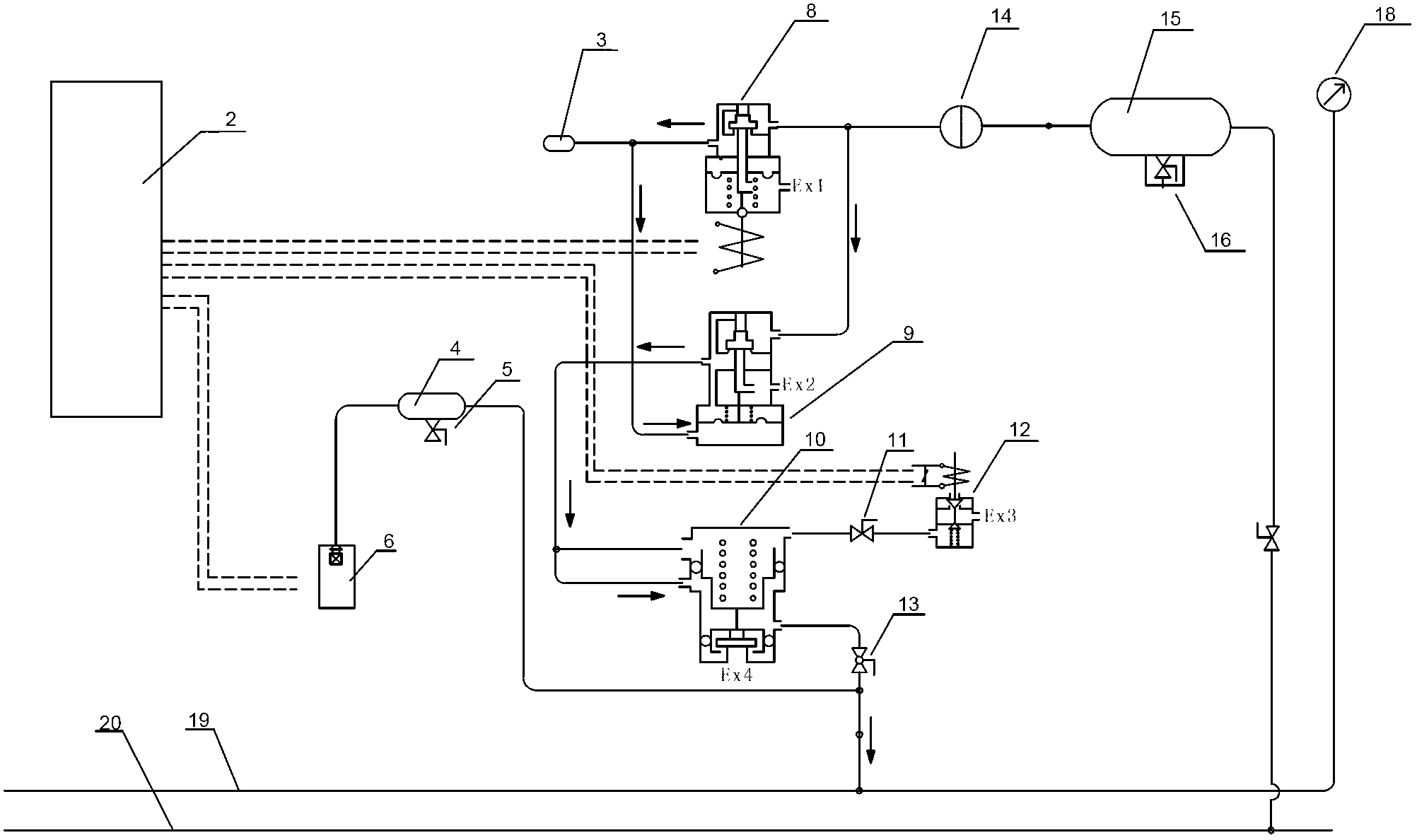
[0021] Such as figure 1 As shown, the high-speed train rescue switching device includes: an electronic control unit 2, an electrop...


PUM


Abstract

A high speed train rescue conversion device comprises an electronic control unit, an electric pneumatic conversion valve, a relay valve, a discharge valve and an emergency electromagnetic valve. The electronic control unit collects train pipe pressure and outputs current signals used for braking, and the electric pneumatic conversion valve converts the received current signals into corresponding precontrol pressure signals and transmits the precontrol pressure signals to a braking pressure input port of the relay valve. Flow amplification of the precontrol pressure signals is carried out by the relay valve, and then the precontrol pressure signals are respectively input into an upper cavity and a lower cavity of the discharge valve. The lower cavity of the discharge valve is connected with a train pipe after blocked and cocked, and the upper cavity of the discharge valve is connected with the emergency electromagnetic valve. A supply pressure input port of the electric pneumatic conversion valve and a supply pressure input port of the relay valve are respectively connected with a pressure supply output port of a main air reservoir (MR). Air valves and the electronic control unit are combined into a whole, synchronization pressure reduction braking of a train with the high speed train rescue conversion device and other trains is achieved, and purposes that device integration and braking sensitivity are promoted, horizontal impulses of the train are reduced, bogie equipment is protected, and braking effect of the train is promoted are achieved.

Description

technical field [0001] The invention relates to a high-speed train rescue switching device, which belongs to the technical field of brake control systems in high-speed trains. Background technique [0002] At present, the CRH2 high-speed EMUs in China's high-speed trains adopt rescue mode in the event of electro-pneumatic through-brake failure. The driver controls the mechanical brake valve to decompress or boost the pressure of the train pipe (BP pipe) to realize the Group braking or relief. If the mechanical brake valve of the faulty car fails to work, it can still be connected to the faulty car through the train pipe of the rescue locomotive or a functionally complete EMU. , to control its own air distribution valve, so that the main air duct can fill or exhaust the brake cylinder to achieve braking or release operation. This device can rescue the vehicle or other vehicles with BP pipes, but its performance, response time and accuracy depend on its own air circuit and m...

Claims


Application Information

Patent Timeline
Patent Type & Authority Applications(China)
IPC IPC(8): B61H11/06
Inventor 孙环阳杨俊杨硕刘寅虎
Owner NANJING CRRC PUZHEN HAITAI BRAKE EQUIP CO LTD
Why Eureka
Try Eureka