Outer rotor electronic control fan and speed regulating method

An external rotor fan and electronic control technology, which is applied in pump control, mechanical equipment, non-variable pumps, etc., can solve the problems of small heat dissipation, poor heat dissipation effect, and inapplicability, so as to ensure reliable operation and realize dust prevention The effect of sealing and low manufacturing cost

Active Publication Date: 2013-03-20
HANGZHOU DUNLI ELECTRIC APPLIANCES
View PDF14 Cites 8 Cited by
  • Summary
  • Abstract
  • Description
  • Claims
  • Application Information

AI Technical Summary

Problems solved by technology

Its disadvantages: It is impossible to realize isolated speed regulation, and the fan power system is easy to burn out
Its disadvantages: The stepless speed regulation driver is a single-stage heat dissipation structure, with small heat dissipation and poor heat dissipation effect, and is not suitable for heat dissipation of intelligent power modules in the electronic control circuit of outer rotor fans.
Its disadvantages: the heat dissipation structure of the three-phase half-controlled rectifier bridge has small heat dissipation and poor heat dissipation effect, and is not suitable for heat dissipation of the rectifier bridge in the electronic control circuit of the outer rotor fan
Its shortcoming: this structure is not suitable for the installation of the Hall sensor in the speed regulation circuit used by the outer rotor fan
Its shortcomings: neither can the speed control circuit board be installed in the casing, nor can it realize the simple and reliable connection between the stator coil and the speed control circuit board in the stator winding
Its disadvantages: First, the volume is large, which affects the use effect; second, the dustproof effect is not good

Method used


Image

  • Outer rotor electronic control fan and speed regulating method
  • Outer rotor electronic control fan and speed regulating method
  • Outer rotor electronic control fan and speed regulating method

Examples


Embodiment 1

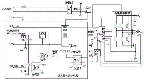
[0032] Embodiment 1: with reference to attached figure 1 . An electronically controlled outer rotor fan, including an outer rotor fan, the speed regulation circuit of the outer rotor fan includes an AC-direct power conversion circuit, an isolation characteristic speed regulation circuit, an overvoltage protection circuit and an intelligent power control module; the isolation characteristic speed regulation circuit The power output terminal of the isolated power supply outputs +10V power supply, the ground terminal GND2 of the isolated power supply is connected to the ground terminal of the operational amplifier chip Ⅰ, the ground terminal of the comparator chip Ⅱ, the signal output terminal of the optocoupler Ⅱ, the negative pole of capacitor C1, and the negative pole of diode D1. The positive pole of capacitor C1 is connected to the signal input terminal of the operational amplifier chip Ⅰ, the positive pole of diode D1 is connected to the speed output terminal, the signal in...

Embodiment 2

[0038] Embodiment 2: On the basis of Embodiment 1, a speed regulation method for the drive circuit of an external rotor electronically controlled fan, using the AC / DC conversion chip 0 to generate power with isolation characteristics for the operational amplifier chip I and the comparator chip Ⅱ provides working power, and the triangular wave signal generated by the operational amplifier chip Ⅰ enters the comparator chip Ⅱ for signal processing to generate a PWM signal, which is then connected to the speed control port of the fan control chip through the optocoupler Ⅰ to realize the speed regulation function , the fan speed signal FG is fed back to the fan user power system in real time through the optocoupler II; the voltage detection circuit is used to detect the VS voltage at the intelligent power control module terminal in real time, when the VS voltage at the intelligent power control module terminal rises, the comparator chip III signal input The voltage at point A of the...


PUM


Abstract

The invention relates to an outer rotor electronic control fan and a speed regulating method. A +10V power supply is output by the power supply output end of an isolating power supply in an isolating characteristic speed regulating circuit; the ground terminal GND2 of the isolating power supply is connected with the ground terminal of an operational amplifier chip I, the ground terminal of a comparator chip II, the signal output end of an optical coupler II, the cathode of a capacitor C1 and the cathode of a diode D1; the anode of the capacitor C1 is connected with the signal input end of the operational amplifier chip I; the anode of the diode D1 is connected with a rotating speed output end; the signal input terminal of the optical coupler II is connected with an FG signal end; the signal end of the isolating power supply is connected with the signal input end of an intelligent power module; the signal output end of the operational amplifier chip I is connected with the signal input end of the comparator chip II; the signal output end of the comparator chip II is connected with the signal input end of an optical coupler I; and the signal output end of the optical coupler I is connected with the signal input end of a logical driving chip of a direct-current brushless fan. The outer rotor electronic control fan and the method have the advantages that the isolating characteristic speed regulation of the outer rotor electronic control fan is realized, and the defect of easiness in burning of a power supply system existing in the prior art is overcome.

Description

technical field [0001] The invention relates to an outer rotor electronically controlled fan and a speed regulating method capable of fundamentally solving the burning of the power system of the outer rotor fan, and belongs to the field of manufacturing speed regulating circuits of the outer rotor fan. Background technique [0002] CN102364114A, the name "a remote-control speed-adjustable external rotor axial flow fan", including fan blades, mesh cover, junction box, motor, is characterized in that: the junction box includes a signal receiving module, a transformer rectifier circuit, a decoding circuit, Motor control circuit, control signal transmitting circuit, control signal receiving circuit, motor control circuit, the transformer and rectifier circuit converts the alternating current into a smaller voltage direct current for each circuit; the control signal transmitting circuit sends the coded signal to the control Signal receiving circuit, the control signal receiving c...

Claims


Application Information

Patent Timeline
Patent Type & Authority Applications(China)
IPC IPC(8): F04D25/08F04D27/00F04D29/58
Inventor 屈刚孙勇皋锦东
Owner HANGZHOU DUNLI ELECTRIC APPLIANCES
Why Eureka
Try Eureka