A power heat pipe central air conditioner

A central air conditioner and power heat pipe technology, applied in the field of air conditioning and refrigeration, can solve problems such as excessive power consumption, increase the pressure difference between the front and back of the compressor, and excessive power consumption, so as to reduce energy consumption, improve heat transfer efficiency, and ensure service life. Effect

Active Publication Date: 2016-06-08
BEIJING FULLLINK OREITH TECH CO LTD
View PDF8 Cites 0 Cited by
  • Summary
  • Abstract
  • Description
  • Claims
  • Application Information

AI Technical Summary

Problems solved by technology

The chilled water system is a closed system that uses water as the cooling medium to exchange energy with air. Although it has less contact with the outside world, an expansion tank is installed at the highest point of the entire system, so that the chilled water medium is still in contact with the air, so that Dissolved oxygen and some nutrients enter the chilled water system, causing slime to deposit and form scale, which will affect heat transfer, which will bring two problems, firstly reduce the cooling effect, 1 mm scale will reduce the cooling capacity by 20- 40%; Secondly, it will increase the pressure of the condenser and increase the pressure difference between the front and back of the compressor, resulting in an increase in the load on the motor and more power consumption. 1 mm of scale will consume 20-30% more power

Method used


Image

  • A power heat pipe central air conditioner
  • A power heat pipe central air conditioner
  • A power heat pipe central air conditioner

Examples


Embodiment 1

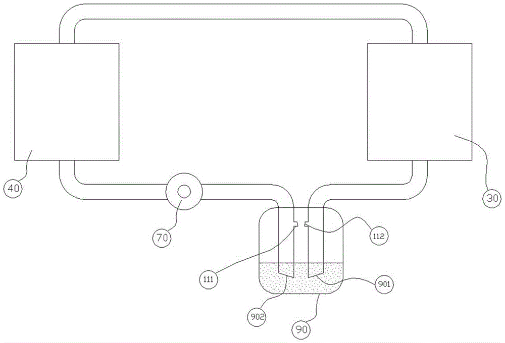
[0023] like image 3 The work flow chart of the first scheme of the power heat pipe circulation system of the present invention is shown, including the second heat exchanger (30), the indoor heat exchanger (40), the first air return hole (111), the second air return hole (112), and the circulation pump (70) and the liquid storage tank (90). When the power heat pipe circulation system works in refrigeration mode, the circulation pump (70) draws a large amount of liquid refrigerant from the liquid storage tank (90) and the part that passes through the air return hole one (111) Supplement a small amount of gaseous refrigerant that is stable throughout the cycle and send it to the indoor heat exchanger (40). The indoor heat exchanger (40) is in contact with the high-temperature heat source, and the liquid working medium is heated by the high-temperature heat source in the indoor heat exchanger (40). Evaporate into gas and absorb heat, the gas formed by evaporation and part of the ...

Embodiment 2

[0025] like Figure 4The work flow diagram of the second scheme of the power heat pipe circulation system of the present invention is shown, including heat exchanger 2 (30), indoor heat exchanger (40), liquid return device (12), circulation pump (70), liquid storage tank (90) and two one-way valves (131, 132), the air inlet of the indoor heat exchanger (40) is connected to the liquid storage tank (90), and the two interfaces (903) are located in the liquid storage tank (90) The upper part of the liquid surface of the working medium, the gas outlet of the second exchanger (30) is connected to the liquid storage tank (90), and the interface (904) of the two is located at the upper part of the liquid surface of the working medium in the liquid storage tank (90); the liquid return device The liquid inlet end of (12) is connected to the liquid storage tank (90), and the two interfaces (905) are located at the lower part of the liquid surface of the working medium in the liquid stor...


PUM


Abstract

The invention provides a power heat pipe type central air conditioner, comprising a large compressor, a four-way valve, a throttle valve, a front end water circulation system and a terminal power heat pipe type circulation system; the front end water circulation system is composed of a heat exchanger one and a circulating water pump The terminal power heat pipe circulation system is composed of heat exchanger 2, indoor heat exchanger and circulation pump; the large compressor connected with four-way valve 1 is connected to the front end water circulation system and the terminal power heat pipe circulation at the same time system; the throttle valve is connected to the front-end water circulation system and the end power heat pipe circulation system at the same time; in this way, the whole system can be cooled and heated. When heating is required, the terminal of the front-end water circulation system is connected to the heat source equipment.

Description

technical field [0001] The invention belongs to the technical field of air conditioning and refrigeration, and in particular relates to a power heat pipe type central air conditioner. Background technique [0002] With the rapid growth of my country's national economy, central air conditioners are widely used, especially in urban hotels, restaurants, large shopping malls, entertainment venues, large office buildings, office buildings, and modern production workshops. With the tasks of cooling in summer and heating in winter, it not only brings people a comfortable environment, but is also used to adjust the temperature and humidity of the environment required for industrial production. Central air-conditioning circulating water system includes cooling water system, chilled water system and heating water system. The chilled water system is a closed system that uses water as the cooling medium to exchange energy with air. Although it has less contact with the outside world, an...

Claims


Application Information

Patent Timeline
Patent Type & Authority Patents(China)
IPC IPC(8): F25B29/00F25B41/04F25B41/06F24F5/00
Inventor 祝长宇丁式平
Owner BEIJING FULLLINK OREITH TECH CO LTD
Why Eureka
Try Eureka