
Dynamic compaction machine, ramming depth measuring method and device of dynamic compaction machine

A technology of ramming depth and measurement method, which is applied in the field of construction machinery, can solve problems such as difficult elimination, casualties, stolen hammers and missed hammers, etc., and achieve the effects of optimizing the construction process, avoiding excessive ramming, and saving labor costs

Active Publication Date: 2013-12-18
SANY HEAVY IND CO LTD (CN)
View PDF6 Cites 0 Cited by
  • Summary
  • Abstract
  • Description
  • Claims
  • Application Information

AI Technical Summary

Problems solved by technology

[0006] 1) The site conditions of the dynamic compaction site are very harsh, and the measuring instruments and personnel are relatively close to the dynamic compaction machine, which may easily cause casualties;
[0007] 2) The measurement accuracy and data record accuracy are affected by the human factors of the measurement recorder, and the measurement record transmission process is cumbersome, requiring the surveyor to calculate and judge;
[0008] 3) Manual measurement reduces construction efficiency and increases labor costs;
[0009] 4) It is difficult to measure when the light is poor, especially when construction is required at night;
[0010] 5) The actual existence of the eccentric hammer, the transformation of the measuring point of the tower foot, the verticality error of the erected tower foot, and the accumulation of soil on the top surface of the hammer all make the measurement error objectively exist, and it is difficult to eliminate;
[0011] 6) There is a phenomenon of hammer stealing and missing hammer, which cannot be automatically supervised

Method used


Image

  • Dynamic compaction machine, ramming depth measuring method and device of dynamic compaction machine
  • Dynamic compaction machine, ramming depth measuring method and device of dynamic compaction machine
  • Dynamic compaction machine, ramming depth measuring method and device of dynamic compaction machine

Examples


Embodiment Construction

[0057] In order to understand the above-mentioned purpose, features and advantages of the present invention more clearly, the present invention will be further described in detail below in conjunction with the accompanying drawings and specific embodiments.

[0058] In the following description, many specific details are set forth in order to fully understand the present invention, but the present invention can also be implemented in other ways different from those described here, therefore, the present invention is not limited to the specific embodiments disclosed below limit.

[0059] The basic idea of ​​the present invention is to provide a dynamic tamping machine and a device for measuring the tamping depth thereof. The device completes the measurement process through the method for measuring the tamping depth of the dynamic tamping machine described herein. In order to facilitate those skilled in the art to understand the technical solution, this paper first describes the m...


PUM


Abstract

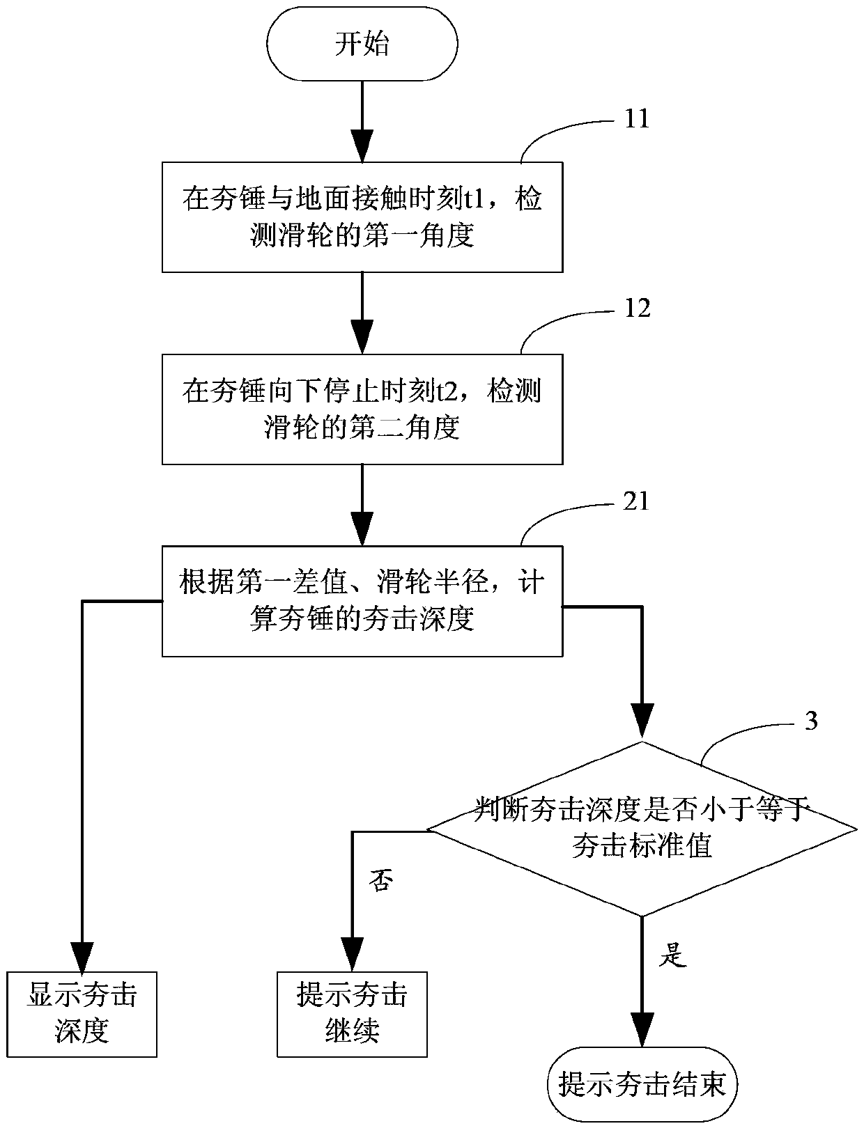
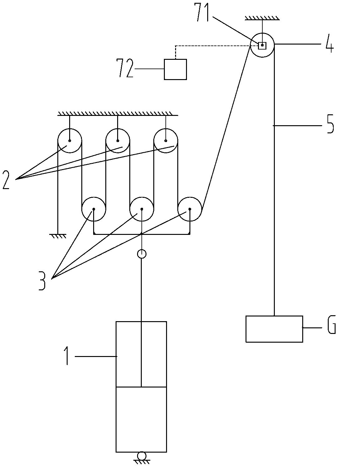
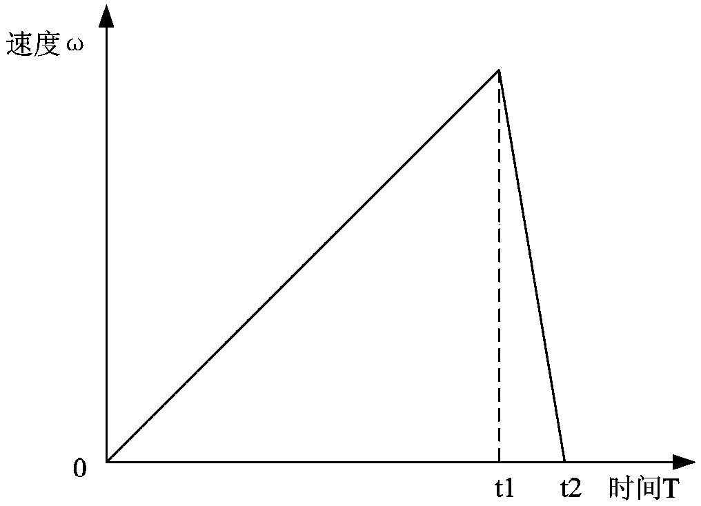
The invention provides a dynamic compaction machine, a ramming depth measuring method and a device of the dynamic compaction machine. The ramming depth measuring device of the dynamic compaction machine is used in a non-unhooked type dynamic compaction machine and comprises an angular displacement detecting device and a processor, the angular displacement detecting device is used for detecting rotation angular displacement of a pulley, and the processor is connected with the angular displacement detecting device and calculates ramming depth of a rammer according to the angular displacement of the pulley and a radius of the pulley. The ramming depth measuring device of the dynamic compaction machine can further comprise a display device and / or an alarming device. By means of the dynamic compaction machine, the ramming depth measuring method and the device of the dynamic compaction machine, automatic measuring of ramming depth can be achieved, the measuring is accurate, the error is small, the reliability is high, the using is convenient, automatic supervising can be achieved, construction of the dynamic compaction machine is optimized, and optimum ramming times can be guaranteed.

Description

technical field [0001] The present invention mainly relates to the field of engineering machinery, in particular to a method and device for measuring the tamping depth of a dynamic tamping machine, and a dynamic tamping machine including the device for measuring the tamping depth of a dynamic tamping machine. Background technique [0002] Dynamic tamping machine is a kind of construction machinery used for impact compaction of materials or foundations, widely used in the construction of industrial and civil buildings, warehouses, yards, docks, airports, road and railway roadbeds, artificial islands, etc. . After the dynamic tamping machine lifts the rammer to the specified height, release the rammer to let it fall freely, so as to give the foundation a strong impact and vibration, destroy the soil and compact it, reduce its compressibility, and improve the soil layer. The degree of uniformity can reduce the differential settlement that may occur in the future. [0003] The...

Claims


Application Information

Patent Timeline
Patent Type & Authority Patents(China)
IPC IPC(8): G01B21/18E02D3/054
Inventor 易小刚张作良李东吴志强
Owner SANY HEAVY IND CO LTD (CN)
Learn More