Simplified sine wave sampling circuit

A sampling circuit and sine wave technology, applied in the field of sine wave sampling circuits, can solve the problems of complex processing process and reduced precision, and achieve the effect of simplifying the circuit, improving the sampling accuracy, and simplifying the design

Active Publication Date: 2013-03-20
EAST GRP CO LTD
View PDF6 Cites 6 Cited by
  • Summary
  • Abstract
  • Description
  • Claims
  • Application Information

AI Technical Summary

Problems solved by technology

[0003] There are two problems in the above implementation method: 1. The signal processing must go through two processes of scaling down and u...

Method used


Image

  • Simplified sine wave sampling circuit
  • Simplified sine wave sampling circuit

Examples


Embodiment Construction

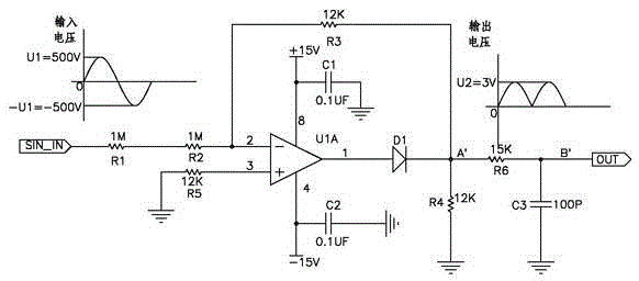
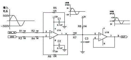
[0018] A simplified sine wave sampling circuit of this embodiment is as figure 1 As shown, it includes an inverting closed-loop amplifier circuit mainly composed of an operational amplifier U1A, an input resistor RA, and a feedback resistor RB. Specifically, the non-inverting input terminal of the operational amplifier U1A takes a reference voltage, and the inverting input terminal of the operational amplifier U1A passes through the input resistor RA respectively. Received to the sampling terminal, connected to the output terminal of the amplifier circuit through the feedback resistor RB,

[0019] When the AC input at the sampling terminal is a negative half-wave, the inverting closed-loop amplifying circuit obtains a reduced inverting output positive voltage proportionally from the sampling voltage through the feedback resistor RB;

[0020] A voltage dividing resistor RC is connected between the output terminal of the amplifying circuit and the ground, and a diode D1 is conn...


PUM


Abstract

A simplified sine wave sampling circuit relates to the technical field of sampling circuits. The simplified sine wave sampling circuit comprises an inverting closed-loop amplifying circuit composed of an operational amplifier U1A, an input resistor RA and a feedback resistor RB. Specifically, the non-inverting input end of the operational amplifier U1A takes reference voltage, the inverting input end of the operational amplifier U1A is connected with the sampling end through the input resistor RA and connected with the amplification circuit output end through the feedback resistor RB, a divider resistor RC is connected between the amplification circuit output end and the ground, and a diode D1 is connected between the inverting input end of the operational amplifier U1A and the amplification circuit output end in series. Compared with the prior art, the sine wave sampling circuit is simplified, sine wave voltage can be reduced to a required range through a first-level operational amplifier, the circuit is simplified, positive half wave input and negative half wave input are both converted into positive voltage output, and amplitude range of voltage half wave output to analog to digital (AD) sampling port of a digital signal processor (DSP) is two times of that in the prior art, and sampling accuracy is improved by one time.

Description

technical field [0001] The present application relates to the technical field of sampling circuits, in particular to a simplified sine wave sampling circuit. Background technique [0002] Since the input voltage of the AD sampling port of the DSP can only be 0~3V, in the prior art, when sampling the mains voltage (220V), it must go through two steps of processing: 1. Scale down the high-voltage sine wave of the mains ;2. Elevate the reduced sine wave so that the entire waveform is between 0~3V; for example figure 2 , when the peak value of the mains voltage is 500V, first reduce the voltage by 3 / 500 and the entire voltage waveform will be within ±3V, then reduce it by 1 / 2 and increase it by 1.5V, and then the entire voltage waveform will be within 0~3V, and finally It is sent to the AD sampling port of the DSP. figure 2 In order to reduce the circuit in proportion to the same phase, it can also be changed into an inverse proportional reduction circuit. [0003] There are ...

Claims


Application Information

Patent Timeline
IPC IPC(8): G01R19/02
Inventor 张涛
Owner EAST GRP CO LTD
Why Eureka
Try Eureka