
Secondary resistance detection circuit of ignition coil

A secondary resistance and ignition coil technology, applied in the direction of measuring resistance/reactance/impedance, measuring devices, measuring electrical variables, etc., can solve problems affecting production efficiency, visual fatigue, etc., reduce human errors, improve production efficiency, method simple and reliable effect

Inactive Publication Date: 2013-03-20
TIANJIN RUIYITAIKE AUTO ELECTRONICS
View PDF5 Cites 2 Cited by
  • Summary
  • Abstract
  • Description
  • Claims
  • Application Information

AI Technical Summary

Problems solved by technology

[0002] The secondary resistance of the ignition coil on the car generally needs to be tested during the production process, the finished product and before leaving the factory. At present, the commonly used detection method is to use the ohm range of the multimeter, but the value on the meter must be read by the operator during the detection process. This will affect production efficiency and easily cause visual fatigue

Method used


Image

  • Secondary resistance detection circuit of ignition coil

Examples


Embodiment Construction

[0017] The ignition coil secondary resistance detection circuit provided by the present invention will be described in detail below with reference to the drawings and specific embodiments.

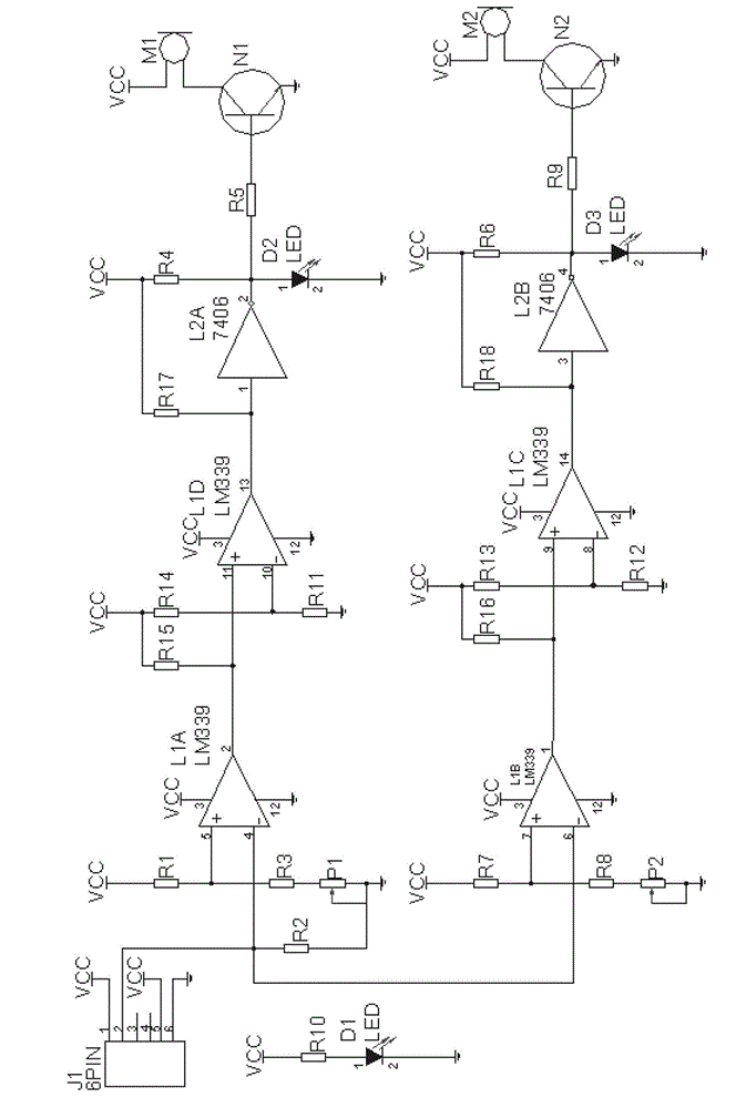
[0018] Such as figure 1 As shown, the ignition coil secondary resistance detection circuit provided by the present invention includes: terminal J1, operational amplifier, inverter, transistors N1, N2, light-emitting diodes D1, D2, D3, resistors R1-R18, adjustable resistors P1, P2, buzzer M1, M2; where:

[0019] Terminal J1 is an input terminal, and its terminals 1 and 2 are test input terminals, which are connected to the secondary side of the ignition coil under test during detection; terminals 1 and 5 of terminal J1 are connected to the power supply VCC, and terminals 6 are connected to the ground wire ;

[0020] The operational amplifiers L1A, L1B, L1C, and L1D are four operational amplifiers in the same package, among which: the non-inverting input terminal 5 of the operational ampli...


PUM


Abstract

A secondary resistance detection circuit of an ignition coil comprises a connection terminal J1, an connection, an inverter, a triode N1, a triode N2, a light emitting diode D1, a light emitting diode D2, a light emitting diode D3, resistors R1-R18, an adjustable resistor P1, an adjustable resistor P2, a buzzer M1 and a buzzer M2. When the secondary resistance detection circuit of the ignition coil is used, testing results can be visually displayed through acoustic and visible signals, testing effects can be obviously improved, and a method is simple and reliable. In addition, the secondary resistance detection circuit of the ignition coil improves production efficiency and reduces human errors in a process for producing the ignition coil on the premise of guaranteeing results of a secondary resistance of the ignition coil to be correct.

Description

technical field [0001] The invention belongs to the technical field of auto parts detection, in particular to an ignition coil secondary resistance detection circuit. Background technique [0002] The secondary resistance of the ignition coil on the car generally needs to be tested during the production process, the finished product and before leaving the factory. At present, the commonly used detection method is to use the ohm range of the multimeter, but the value on the meter must be read by the operator during the detection process. This will affect production efficiency and easily cause visual fatigue. Contents of the invention [0003] In order to solve the above problems, the object of the present invention is to provide a secondary resistance detection circuit of an ignition coil. [0004] In order to achieve the above object, the ignition coil secondary resistance detection circuit provided by the present invention comprises: connecting terminal J1, operational a...

Claims


Application Information

Patent Timeline
IPC IPC(8): G01R27/02
Inventor 包鹏宇
Owner TIANJIN RUIYITAIKE AUTO ELECTRONICS
Learn More