Asynchronous motor rotor time constant on-line identification system and method

A rotor time constant, asynchronous motor technology, used in control systems, control generators, vector control systems, etc., can solve problems such as changes in stator resistance resistance, affecting motor control accuracy, etc., to improve torque control accuracy and improve the effect. Effect

Active Publication Date: 2013-03-20
SUZHOU INOVANCE TECH CO LTD
View PDF5 Cites 12 Cited by
  • Summary
  • Abstract
  • Description
  • Claims
  • Application Information

AI Technical Summary

Problems solved by technology

[0005] The technical problem to be solved by the present invention is to provide an online identification system and method for the rotor time constant of an asynchronous motor in view of the above-mentioned problem that the resistance value of the stator resistance changes due to temperature rise and affects the control accuracy of the motor

Method used


Image

  • Asynchronous motor rotor time constant on-line identification system and method
  • Asynchronous motor rotor time constant on-line identification system and method
  • Asynchronous motor rotor time constant on-line identification system and method

Examples


Embodiment Construction

[0036] In order to make the object, technical solution and advantages of the present invention clearer, the present invention will be further described in detail below in conjunction with the accompanying drawings and embodiments. It should be understood that the specific embodiments described here are only used to explain the present invention, not to limit the present invention.

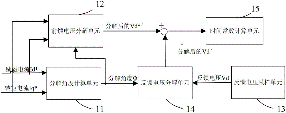
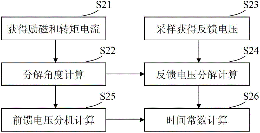
[0037] The invention utilizes the voltage re-decomposition technology to re-decompose the D-axis and Q-axis voltages of the rotating coordinate system. Since the re-decomposed D-axis voltage does not include the stator resistance component, the rotor time constant can be identified and updated online by comparing the decomposed command voltage (feedforward voltage) and feedback voltage using model reference adaptive technology.

[0038] like figure 1 Shown is a schematic diagram of an embodiment of the online identification system for the rotor time constant of an asynchronous motor according to t...


PUM


Abstract

The invention provides an asynchronous motor rotor time constant on-line identification system. The system comprises a decomposition angle calculation unit, a feedforward voltage decomposition unit, a feedback voltage sampling unit, a feedback voltage decomposition unit and a time constant calculation unit, wherein the decomposition angle calculation unit is used for acquiring a decomposition angle according to exciting current and torque current; the feedforward voltage decomposition unit is used for performing decomposition calculation on the feedforward voltage by using the decomposition angle; the feedback voltage sampling unit is used for sampling the output end of a controlled motor to acquire the feedback voltage; the feedback voltage decomposition unit is used for performing decomposition calculation on the feedback voltage by using the decomposition angle; and the time constant calculation unit is used for calculating and updating the rotor time constant according to the decomposition results of the feedforward voltage and the feedback voltage. The system realizes on-line real-time identification of the rotor time constant through voltage decomposition, and the process is not influenced by the change of stator resistance.

Description

technical field [0001] The invention relates to the field of motor control, and more specifically relates to an asynchronous motor rotor parameter online identification system and method. Background technique [0002] In the rotor field-oriented control of asynchronous motors, if the correct decomposition of torque current and excitation current is to be realized, an accurate rotor time constant must be obtained. The inductance and rotor resistance of the motor can be accurately measured through off-line identification, so that the high-precision rotor time constant can be calculated. However, in practical applications, when the asynchronous motor drives a load, the motor itself will generate heat, which will cause the temperature of the motor rotor resistance to rise and cause the motor rotor resistance to change. In this case, if the motor rotor time constant is not corrected online, the torque current and excitation current will not be correctly decomposed, which will di...

Claims


Application Information

Patent Timeline
Patent Type & Authority Applications(China)
IPC IPC(8): H02P21/14H02P21/16
Inventor 何俊辉
Owner SUZHOU INOVANCE TECH CO LTD
Why Eureka
Try Eureka