

Vertical bucket internal and external washing machine
A technology for washing machines and buckets, which is applied in the directions of cleaning hollow objects, cleaning methods and utensils, chemical instruments and methods, etc., can solve problems such as inability to remove dirt and inability to achieve decontamination effects, and achieves cleaning without dead ends and speed. Quick, change the effect of the work environment
Inactive Publication Date: 2013-03-27
宋树建
View PDF0 Cites 31 Cited by
- Summary
- Abstract
- Description
- Claims
- Application Information
AI Technical Summary
Problems solved by technology
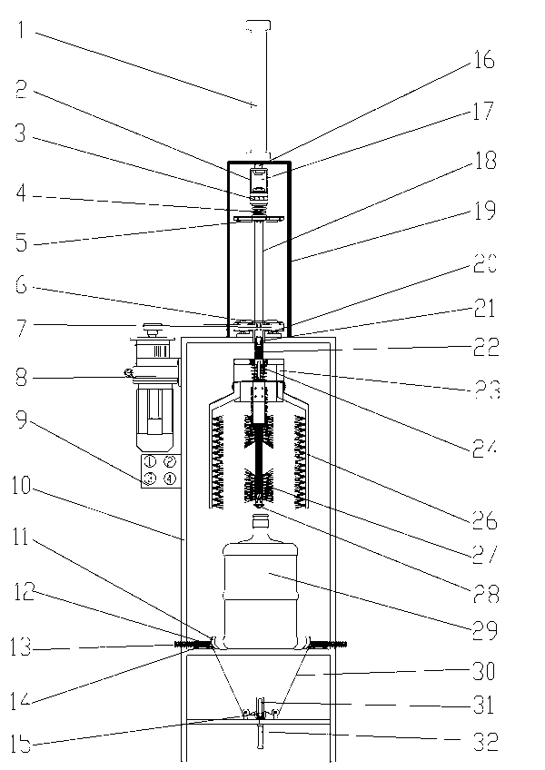
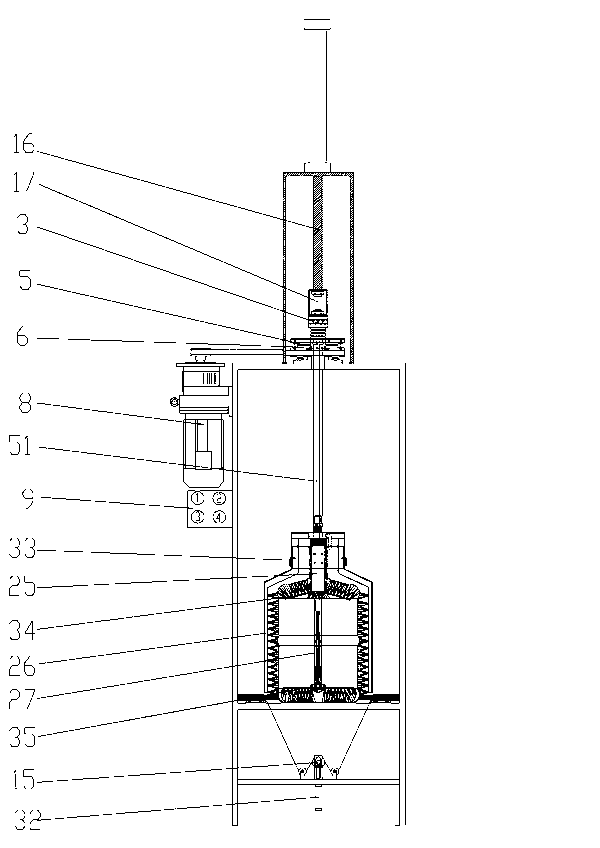
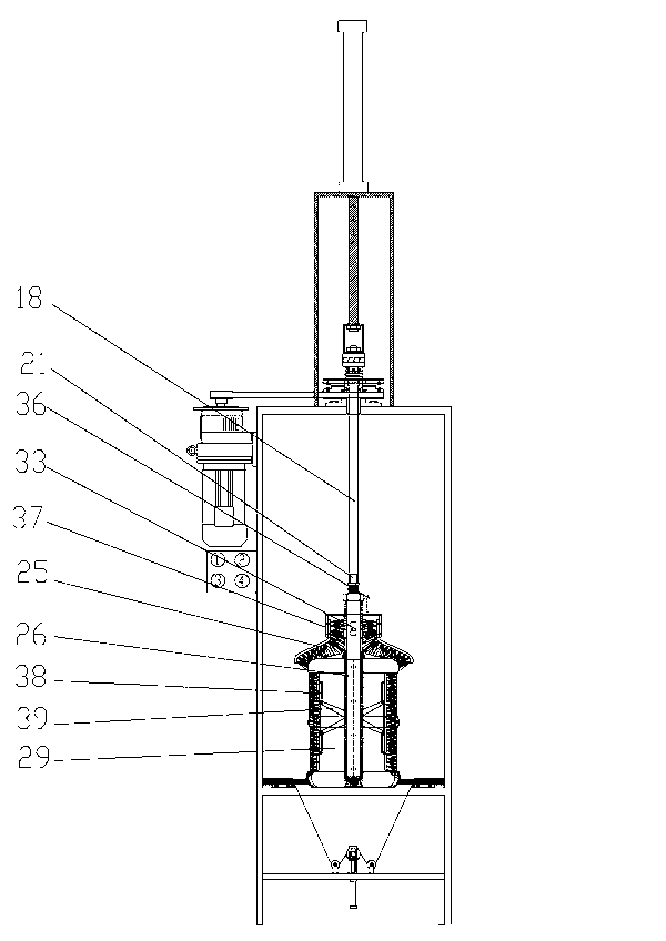
The present invention provides a brush that can automatically enter the bucket through the mouth of the bucket and automatically expand so that the brush can quickly and automatically rotate, spray water, and clean all parts of the bucket wall, bucket bottom, bucket shoulder and outside the bucket. The cleaning operation of a bucket can be completed within one day, and the semi-automatic pure water bucket cleaning machine inside and outside the cleaning machine is completely clean and has no dead angle. Tie a rag to one end of an iron rod or a wooden stick and put it in a bucket to remove the dirt in the bucket little by little by manpower. Some dirt that is smaller or even invisible to the naked eye cannot be removed at all. Some manufacturers produced it a few years ago. A kind of washing machine was developed, which is to tie some nylon wool on the iron rod and use the motor to drive it to rotate in the bucket, and the decontamination effect cannot be achieved at all. Composed of frame, motor, brushes inside and outside the bucket, bucket clamping device, etc. It is characterized in that: when the button on the switch is pressed, the motor drives the pulley to rotate, because there is a center hole larger than the diameter of the driving shaft in the middle of the pulley, and the pulley is installed on the On the bearing seat of the pulley, when the motor drives the pulley to rotate, the driving shaft stops rotating in the center hole of the pulley. When the staff puts the bucket in the cleaning position and presses the button on the switch, the air intake of the bucket clamping cylinder works, pushing The sliding wheel in the pulley seat slides upwards, pulls the tension bar of the barrel clamp to make the barrel clamp installed in the barrel clamp seat squeeze the bottom of the bucket axially, and the bucket clamp installed at the front end of the barrel clamp shaft clamps the bottom of the bucket tightly At the same time, the cylinder shaft of the cylinder pushes down the connecting seat, the thrust bearing, and the driving shaft connected to it to slide downward, and the guide head of the brush shaft guides the mouth of the bucket so that the brush shaft in the bucket enters the bucket smoothly. When the mouth of the bucket When it is squeezed to the pressure seat of the barrel mouth, the brush shaft inside the barrel, the brush seat on the outer wall of the barrel and the brush on the outer wall of the barrel stop going down. Slide down in the bushing of the brush central axis, so that the bottom brush push-pull piece on the central push-pull rod connected with the brush central axis pushes the brush at the bottom of the inner bucket to the washing bucket position at the bottom of the inner bucket. Figure 4 , Figure 5 As shown, the pole push-pull piece and the bucket inner wall brush seat connected with it are pushed to the two side inner walls of the bucket, see Figure 6 As shown, the inner barrel shoulder brush is pushed to the inner shoulder of the barrel by the push-pull groove at the lower end of the brush axis, see Figure 5 As shown, at this time, because the mouth of the bucket has been set on the pressure seat of the bucket mouth, and is supported by the thrust bearing of the bucket mouth, the pressure spring of the thrust bearing, and the pressure spring of the brush seat on the outer shoulder of the bucket, the inner and outer brush shafts of the bucket, the brush seat, The brushes stop sliding downwards, and the brush return spring on the central axis of the brush at the connection with the driving shaft is pressed together. When the stroke of the cylinder reaches the end, the passive clutch plate installed on the driving shaft is in the passive position. Under the action of the clutch plate compression spring, it is tightly squeezed on the rotating active clutch plate, driving the drive shaft and the inner and outer brushes of the bucket to rotate, and at the same time, the high-pressure cleaning water entering the central water hole through the rotating water pipe joint is sprayed from the bucket The water hole, the water spray pipe outside the bucket, sprays to various cleaning parts inside and outside the bucket. When the bucket is cleaned, press the button on the switch, and the cylinder axially pulls the driving shaft upward. The clutch plate is separated, the driving shaft stops rotating, the brush return spring springs open, the central axis of the brush is pulled, and the center push-pull rod moves upwards, so that the washing bucket brush in each part of the bucket is tightly shrunk onto the brush shaft in the bucket, and from the Lift out the bucket easily, press the button on the switch, the bucket cylinder stops pushing the sliding wheel, and the bucket shaft slides outward under the action of the bucket shaft spring, the bucket piece is released from the bottom of the bucket, take it down and clean it When the bucket is removed from the machine after cleaning, the outer shoulder brush seat of the bucket installed in the guide groove will slide down because there is no support for the bucket. The function of the positioning pin is to lock the outer shoulder brush seat of the bucket. Will not fall off in the guide groove
Method used
View moreImage
Smart ImageViewing Examples

Examples
Embodiment Construction
Login to View More PUM
 Abstract
The invention provides a vertical bucket internal and external washing machine. The invention relates to purified water bucket washing equipment and particularly relates to a half-automatic purified water bucket internal and external washing machine, which can automatically expand, rotate and contract inside a bucket and can wash the bucket internally and externally. The problem existing in a background technology that the de-dusting effect cannot be reached because the buckets of large-scale and small-scale purified water plants in China are washed by an original washing method, namely smashed cloth bounded by one end of an iron rod or a wooden rod is placed in the buckets, and dust inside the buckets is entirely removed, can be solved. The vertical bucket internal and external washing machine provided by the invention adopts the technical scheme for solving the technical problem: the vertical bucket internal and external washing machine mainly consists of an air cylinder, a rack, a motor, brushes inside and outside the bucket, a bucket clamping device and the like, wherein the brushes can be automatically expanded and rotated within the bucket, so that the speed is high, no dead angle exists in a washing process, the health quality of drinking water is greatly improved, and the working condition of the water plants can be changed to a certain extent.
Description
technical field [0001] The invention relates to a cleaning device for a pure water bucket, more specifically a semi-automatic inside and outside cleaning machine for a pure water bucket that can automatically expand, rotate, and shrink in the bucket, and can simultaneously clean the inside and outside of the bucket. Background technique [0002] At this stage, the cleaning of buckets in various pure water plants in my country still stays in the original cleaning method, which is to tie a rag to one end of an iron rod or a wooden stick and put it into the bucket, and manually remove the dirt in the bucket little by little. Some small or invisible dirt cannot be removed at all. In the past few years, some manufacturers produced a barrel washing machine, which is to tie some nylon wool on the iron rod and rotate it in the barrel with a motor, which cannot be reached at all. Decontamination effect, so many water plants buy a bucket washing machine to cope with the inspection of t...
Claims
Login to View More Application Information
Patent Timeline
 Patent Type & AuthorityApplications(China)
IPC IPC(8): B08B9/36
Inventor宋树建
Owner宋树建