Swing type diameter changing mechanism of spring machine

A spring machine and swing type technology, which is applied in the field of spring winding machinery, can solve the problems that the precision and stability of the spring cannot be properly guaranteed, it is difficult to effectively control the quality of the spring, and the rigidity and stability of the winding mechanism can be reduced. , to achieve the effect of convenient adjustment, good overall rigidity and high degree of intelligent operation

Active Publication Date: 2013-03-27
浙江创宇机械科技有限公司
View PDF6 Cites 0 Cited by
  • Summary
  • Abstract
  • Description
  • Claims
  • Application Information

AI Technical Summary

Problems solved by technology

But no matter where it moves, the angle of inclination between the ejector rod and the vertical direction is fixed, that is, the direction of force applied to the steel wire is always the same. When the ejector rod moves to the limit position of the edge machine, for example, the upper left corner Or the lower right corner, the steel wire will break away from the groove at the front end of the ejector rod and contact the side of the ejector rod. In this way, the manufacturing accuracy and stability of the spring cannot be guaranteed, making it difficult to effectively control the quality of the spring
Moreover, the two groups of slide plate devices of this structure are stacked up and down, so that the diameter-reducing mechanism is increased, and the rigidity of the horizontal thrust transmission link of the slide plate is reduced; The output is more, which greatly reduces the rigidity and stability of the winding mechanism. This defect is especially prominent when winding large and medium-sized springs.

Method used


Image

  • Swing type diameter changing mechanism of spring machine
  • Swing type diameter changing mechanism of spring machine
  • Swing type diameter changing mechanism of spring machine

Examples


Embodiment 1

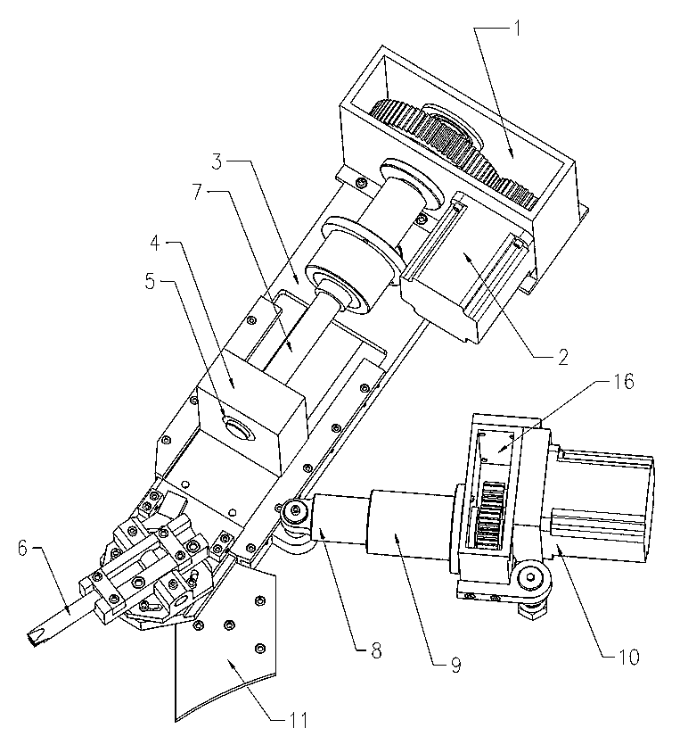
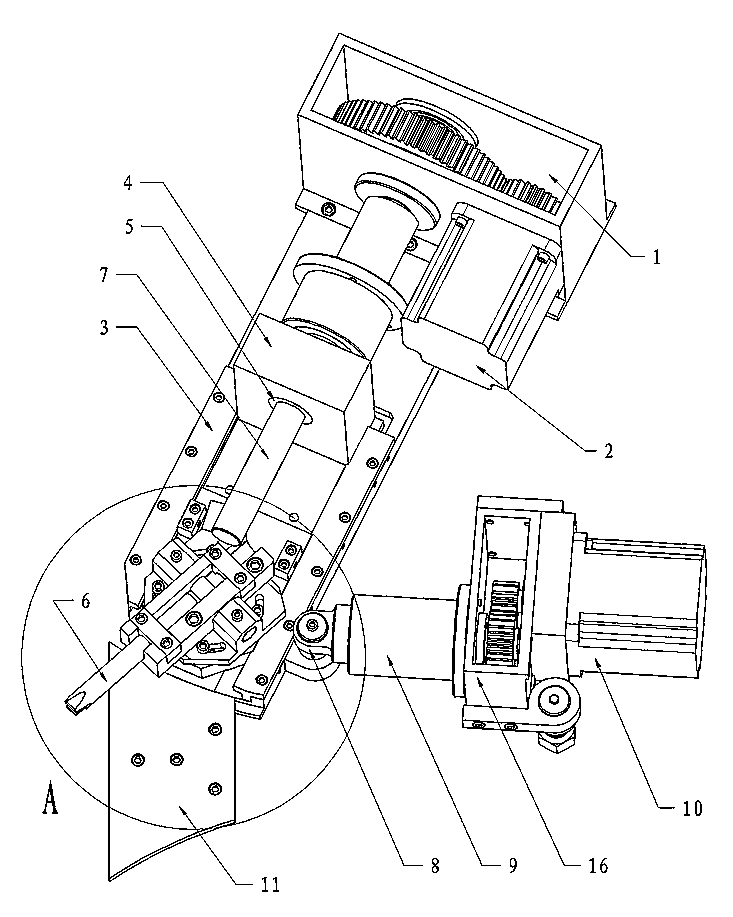
[0026] The swing reducing mechanism of the spring machine is as follows: figure 1 - Figure 6 As shown, it includes a slide-type ejector rod swing device and a connecting rod telescopic swing device; each set of devices has a pin shaft connected to the front wall of the spring machine under the base, and can rotate and swing around the respective pin shafts;

[0027] The slide plate type ejector rod swing device includes a slide seat 3, a slide plate 4, and a motor Ⅰ connected to the reduction box 1. The slide plate 4 is fixed with the ejector rod 6 and the screw nut 5, and the slide seat 3 is fixed on the output shaft of the reduction box 1. The screw Ⅰ is fixed, and the screw Ⅰ and the screw nut 5 are screwed together. When the screw Ⅰ rotates, it can drive the screw nut 5 and the slide plate 4 together with the ejector rod 6 to advance and retreat together;

[0028] The motor II connected to the reduction box II is fixed on the base of the connecting rod telescopic swing d...

Embodiment 2

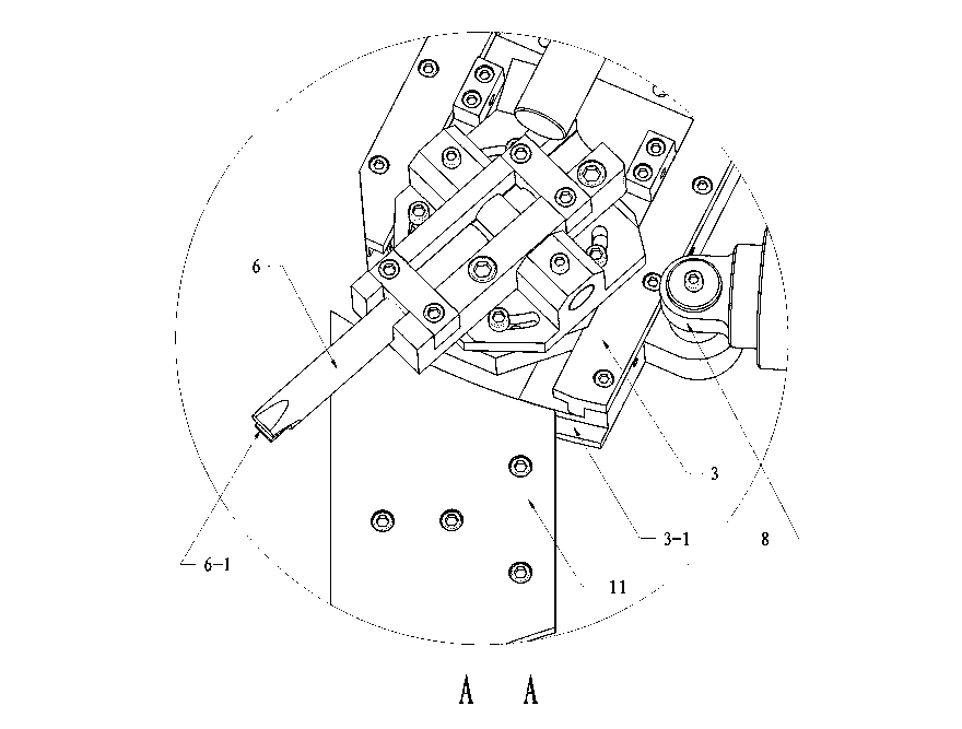
[0031] Embodiment 2, the basic structure movement mode is the same as that of Embodiment 1, the only difference is that an arc-shaped sliding tenon concentric with the axis line of the sliding seat pin shaft 15 is set at the front end of the sliding seat 3 of the sliding plate type ejector rod swing device 3-1, the pressing plate 11 adapted to the arc-shaped sliding tenon 3-1 is fixed on the front wall of the spring machine, such as image 3 As shown, the swing trajectory of the slide-type ejector rod swing device is more accurate, and the stability and rigidity of the diameter-changing mechanism are significantly improved.

[0032] As a preferred solution, the swing-type reducing mechanism of the present invention can be arranged in an array on the front wallboard of the spring machine, and the push rods 6 on each set of swing-type reducing mechanism can be adjusted to different directions respectively to adapt to the multi-axis spring machine. Process requirements, depending...


PUM


Abstract

A swing type diameter changing mechanism of a spring machine comprises a sliding plate type post rod swing device and a connecting rod flexible swing device, and a hinge pin of the sliding plate type post rod swing device is connected onto a front wall plate of the spring machine. A post rod and a lead screw nut are fixed on a sliding plate of the sliding plate type post rod swing device, and when a lead screw I fixed on a reduction gearbox output shaft rotates, the post rod is driven to advance and retreat. A cylinder body arranged at the rear end of a connecting rod of the connecting rod flexible swing device can slide in an inner wall of a guide sleeve, and when a lead screw II fixed on the reduction gearbox output shaft rotates, the connecting rod can be driven to advance and retreat. The front end of the connecting rod and a slide rest hinge pin are connected, the slide rest is driven by the connecting rod to swing during advancing and retreating of the connecting rod, and the sliding plate and the connecting rod are controlled to advance and retreat respectively by a programmable logic controller. The sliding plate type post rod swing device and the connecting rod flexible swing device can separately swing, accordingly inclination angle of the post rod is changed all along during the moving process, and further the best force application direction to steel wires can be guaranteed. An arc-shaped sliding tenon arranged at the front end of the sliding slide rest and a pressing plate fixed on the front wall plate are matched, and accordingly swing track of the sliding plate type post rod swing device is more accurate.

Description

technical field [0001] The invention relates to the field of spring winding machinery, in particular to a swing-type diameter-reducing mechanism of a spring machine. Background technique [0002] The reducing mechanism is a key part that must be possessed by the steel wire spring winding machine. During the spring winding process, the steel wire is forced to be sent out and moves in one direction. There must be a push rod or roller of the reducing mechanism in several positions and from different directions. Push the steel wire upward to change the forward direction of the steel wire so that the steel wire can be wound into a spring. To wind various springs with different outer diameters and different rotation directions, it is necessary to adjust the force application direction and force application position of each ejector pin. As a result, a movable spring machine variable diameter mechanism has appeared on the domestic market. Its basic features are: there is a vertica...

Claims


Application Information

Patent Timeline
Patent Type & Authority Applications(China)
IPC IPC(8): B21F35/00
Inventor 李超
Owner 浙江创宇机械科技有限公司
Why Eureka
Try Eureka