Control circuit of dot matrix printer

A dot matrix printer and control circuit technology, applied in printing devices, printing, etc., can solve the problems of high cost, large capacity and high cost, etc., achieve the effects of reducing performance requirements, ensuring effective control, and reducing the amount of software changes

Active Publication Date: 2019-01-04
FUJIAN LANDI COMML EQUIP CO LTD
View PDF7 Cites 0 Cited by
  • Summary
  • Abstract
  • Description
  • Claims
  • Application Information

AI Technical Summary

Problems solved by technology

[0006] The above scheme uses the FPGA chip to control the printer, but all the control of the print head and the control of the paper / carriage motor in this scheme are realized through FPGA, which requires the use of high-end FPGA chips with large capacity, high cost, and a large number of IOs. achievable, cost prohibitive

Method used


Image

  • Control circuit of dot matrix printer
  • Control circuit of dot matrix printer
  • Control circuit of dot matrix printer

Examples


Embodiment 1

[0048] Please refer to Figure 2 to Figure 5 , Embodiment 1 of the present invention is:

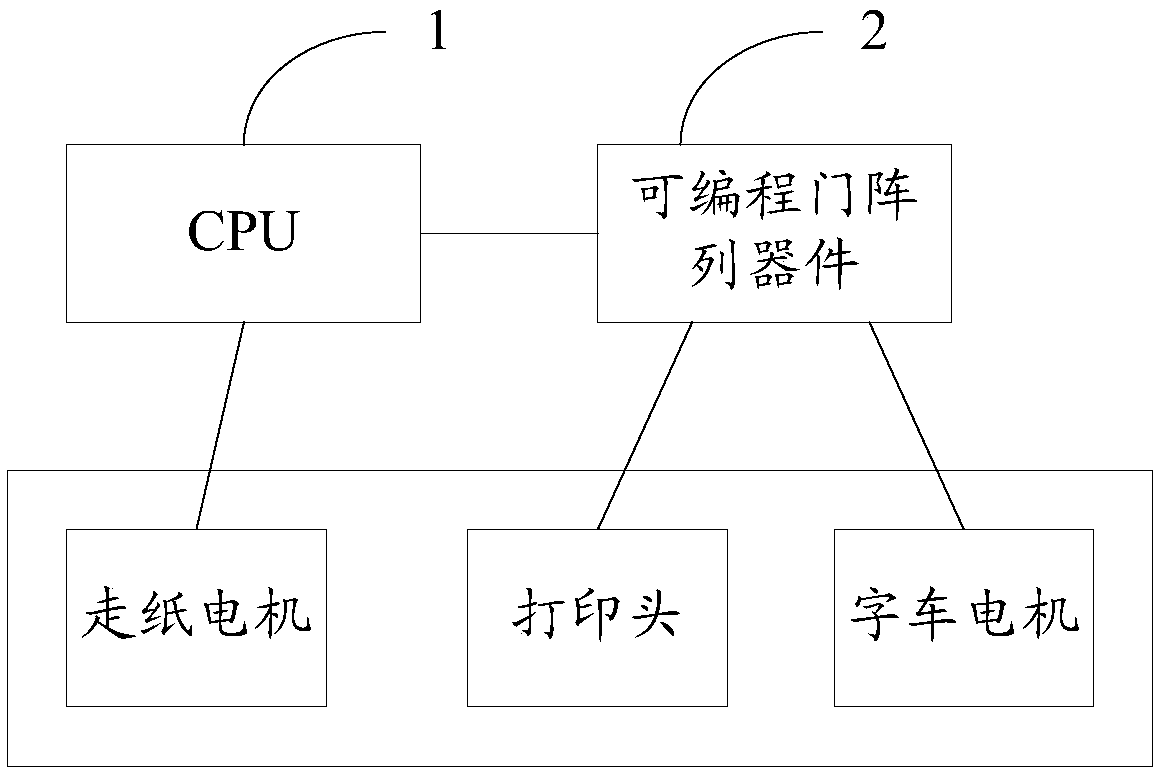
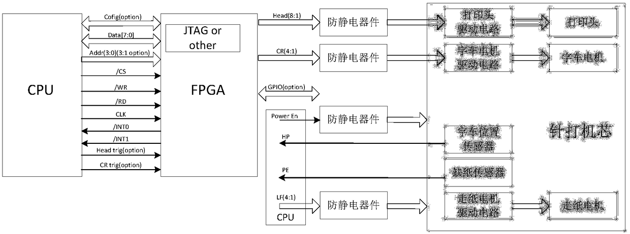
[0049] A control circuit of a dot matrix printer, externally connected to a dot matrix printer, comprising: a CPU needle and an FPGA, the CPU is connected to a paper feed motor of the dot matrix printer, and the FPGA is respectively connected to a print head and a character carriage motor of the dot matrix printer; specifically , the CPU is connected to the dot-type printer’s dot-printing movement through the paper-feeding control line; the FPGA is connected to the dot-striking movement through the character car control line and the needle output control line; at the same time, the CPU and the FPGA are connected through the data communication line and Interrupt line connections, such as figure 2 shown.

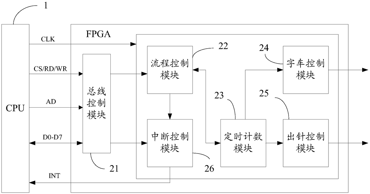
[0050] The data transfer between the above CPU and FPGA is realized through an 8-bit data bus, which is composed of one address line, eight data lines, read signal, write signal and c...


PUM


Abstract

The invention provides a control circuit of a needle printer. The control circuit of a needle printer comprises a CPU and a field programmable gate array device; the CPU is connected with each of the field programmable gate array device and a paper feeding motor of the needle printer; the field programmable gate array device is connected with each of a carriage unit motor and a printing head of the needle printer; the CPU is used for processing data to be printed, calculating to obtain a printing command and a paper feeding command, transmitting the printing command to the field programmable gate array device, and transmitting the paper feeding command to the paper feeding motor; the field programmable gate array device is used for controlling the carriage unit motor and the printing head to print according to the printing command; the paper feeding motor is used for controlling paper feeding according to the paper feeding command. The control with high real-time requirement is realized by the field programmable gate array device, the control with low real-time requirement is realized by the CPU, the response speed is improved, and the performance requirement of the field programmable gate array device is also reduced, so that the cost is reduced.

Description

technical field [0001] The invention relates to the field of printers, in particular to a control circuit of a dot matrix printer. Background technique [0002] A dot matrix printer is a device that uses a printing needle to print ink dots on printing paper to complete printing. The basic principles are: 1. The print head includes a printing needle and an electromagnet. Under the action of the electromagnet, the printing needle can print ink dots on the printing paper through attraction and release; With the cooperation of relevant mechanical devices, by moving the print head, the position of the printing points can be arranged, so as to realize the printing of specified characters, Chinese characters and graphics. [0003] Dot matrix printers usually consist of two parts, including the mechanical part and the electrical control part. Among them, the electrical control part converts the text and graphic information to be printed into the pulse width signal used to control ...

Claims


Application Information

Patent Timeline
Patent Type & Authority Patents(China)
IPC IPC(8): B41J29/393B41J2/225
CPCB41J2/225B41J29/393
Inventor 夏晓昊任佑林廖泽龙
Owner FUJIAN LANDI COMML EQUIP CO LTD
Why Eureka
Try Eureka