Capacitor assembly welding tool

A technology for capacitors and welders, which is applied in auxiliary devices, manufacturing tools, welding equipment, etc., can solve the problems of electronic assembly efficiency decline, prone to waiting for work, component damage, etc., and achieve electronic assembly efficiency improvement and fixation effect Good, the effect of avoiding damage to components

Inactive Publication Date: 2013-03-27
GLORYMV ELECTRONICS
View PDF0 Cites 2 Cited by
  • Summary
  • Abstract
  • Description
  • Claims
  • Application Information

AI Technical Summary

Problems solved by technology

At this time, if there is a shortage of components or the assembly of the whole machine and the extension is not completed, the assembly and welding operation of the parallel connection of capacitors cannot be carried out, and it is easy to appear waiting for work, which makes the efficiency of elect

Method used


Image

  • Capacitor assembly welding tool

Examples


Example Embodiment

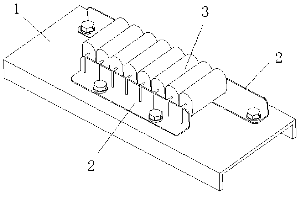
[0011] like figure 1 A capacitor welding tool is shown, comprising a base 1 and two welding strips 2 with an "L"-shaped cross section, and the two welding strips 2 are respectively detachably connected to the base 1 through screws. Two welding bars 2 are arranged parallel to each other, and one of the welding bars 2 is longer than the other. The capacitor welding tool also includes a capacitor 3, and the pins on both sides of the capacitor 3 are welded on the two welding bars 2 respectively.

[0012] When assembling, first assemble the short welding strip and the long welding strip through the fixing fasteners and the welding tool, and fasten the fixing fasteners. The fixing fasteners can be screws. Then, according to the distance between the short welding strip and the long welding strip, the capacitor 3 is formed with pins, and then the capacitor 3 is welded to the short welding strip and the long welding strip. The welding strip as a whole is removed from the welding tool...


PUM


Abstract

The invention discloses a capacitor assembly welding tool which comprises a base and two welding strips with L-shaped sections, wherein the two welding strips are detachably connected to the base through a screw respectively. With the structure, the capacitor assembly welding tool disclosed by the invention has the advantages that (1) the tool is simple and easy to implement and has good fixing effect and low cost; and (2) the electronic assembly efficiency is greatly improved, and the phenomenon of component damage caused by high temperature is avoided.

Description

technical field [0001] The invention relates to the technical field of capacitor welding, in particular to a capacitor welding tool. Background technique [0002] Capacitors are inseparable from the assembly of electronic equipment. In the whole machine or extension, one or more capacitors are more or less connected in parallel to the pins of some components. Wait until the assembly of the whole machine or sub-machine is completed before performing the welding operation of capacitor parallel connection, because this operation is limited by the specific layout and size of the components. At this time, if there is a shortage of components or the complete machine and extension are not assembled, the welding operation of the capacitors connected in parallel cannot be carried out, and the phenomenon of waiting for work is likely to occur, which reduces the efficiency of electronic assembly; in addition, some components cannot withstand the welding process. Under the influence of...

Claims


Application Information

Patent Timeline
IPC IPC(8): B23K37/04
Inventor 程刚史中梁程辉宫龙
Owner GLORYMV ELECTRONICS
Why Eureka
Try Eureka