Robot having workpiece mass measurement function

A mass measurement and robotics technology, applied in the field of robotics, can solve the problem of large cycle time of robots, etc., and achieve the effect of suppressing costs and simple structure

Active Publication Date: 2013-03-27
FANUC LTD
View PDF8 Cites 18 Cited by
  • Summary
  • Abstract
  • Description
  • Claims
  • Application Information

AI Technical Summary

Problems solved by technology

In addition, if the robot 1 is made to stand still so that such gravity and inertial forces do not act, the robot 1 needs deceleration time, rest time, and re-acceleration time.
As a result, the period of robot 1 also becomes considerably larger

Method used


Image

  • Robot having workpiece mass measurement function
  • Robot having workpiece mass measurement function
  • Robot having workpiece mass measurement function

Examples


Embodiment 1

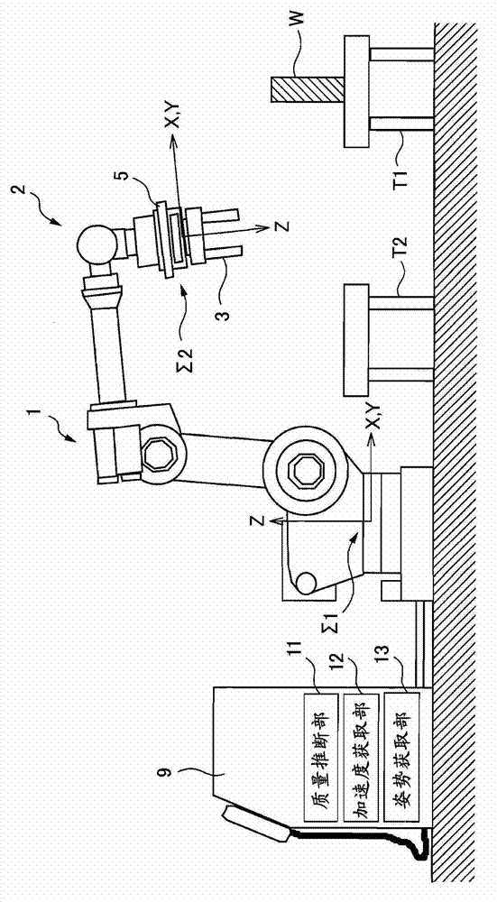
[0059] In the first embodiment, the mass of the hand 3 is known by other measurements. In addition, since a force sensor having three or more axes is used as the force sensor 5 , the force sensor 5 can detect a force of three parallel components.

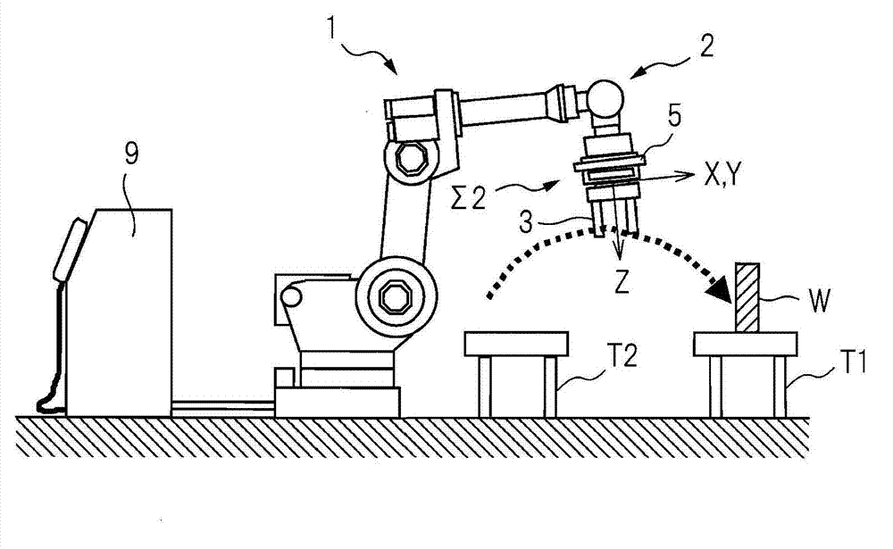
[0060] exist Figure 2B In , the workpiece W is held by the hand 3 of the robot 1, and the robot 1 and the workpiece W operate without contacting peripheral equipment or the like. At this time, if Figure 2B As shown, the output of the force sensor 5 when the robot 1 is operated so that the posture of the wrist of the robot 1 does not change is expressed by the following equation (1). In addition, the reason why the wrist is not changed is to reduce the influence of disturbances such as vibration of the robot.

[0061] F=(Mh+Mw)·R·{g+d 2 x / dt 2 +C(x, dx / dt)} (1)

[0062] Wherein, F is the force vector (detection value) detected by the force sensor 5,

[0063] Mh is the mass of hand 3,

[0064] Mw is the mass of workpiece W, ...

Embodiment 2

[0077] image 3 It is a figure which shows the operation|movement of the robot which concerns on Example 2 of this invention. It can be seen from the figure that the second embodiment is different from the first embodiment in that the acceleration sensor 6 is installed on the base of the hand 3 . In addition, also in the second embodiment, a force sensor with three or more axes is used as the force sensor 5 , so the force sensor 5 can detect a force of three parallel components. In the above-mentioned first embodiment, the vector {g+d is obtained by calculation 2 x / dt 2 +C(x, dx / dt)}, however, in the second embodiment, the above-mentioned vector is obtained by using the output of the acceleration sensor 6 .

[0078] in such as Figure 2B In a state where the robot 1 is holding the workpiece W as shown, the front end portion 2 is moved on a certain track from the table T1 to the table T2. The output of the force sensor 5 at this time can be represented by the following for...

Embodiment 3

[0090] The force sensor 5 used in the third embodiment is a force sensor with more than three axes, capable of detecting parallel three-component force. Example 3 is different from the above-mentioned Example 1 in that it is measured by two steps described later. That is, in the third embodiment, since the mass of the hand 3 is also calculated, it is not necessary to measure the mass of the hand 3 in advance.

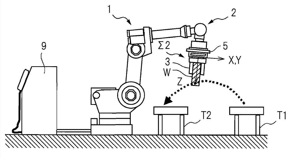
[0091] First, the first step will be described. Such as Figure 2A As shown, in a state where the hand 3 of the robot 1 is not holding the workpiece W, the hand 3 of the robot 1 is moved in the air without contacting peripheral equipment. The output of the force sensor 5 when the robot 1 is operated so that the posture of the wrist of the robot 1 does not change is represented by the following equation (4).

[0092] F1=Mh·R·(g+d 2 x / dt 2 +C(x, dx / dt)) (4)

[0093] Wherein, F1 is the force vector (detection value) detected by force sensor 5,

[0094] Mh is the mass ...


PUM


Abstract

The invention provides a robot having workpiece mass measurement function. Workpiece mass can be correctly obtained, even during operating. A robot (1) having a workpiece mass measurement function for measuring the mass of a workpiece that is held, includes a force measurement unit (5) that measures the force that is applied to the tip part (2) of the mechanism part of the robot (1), and a mass estimation unit (11) that estimates the mass of the workpiece that is held by the robot (1), based on information about the force acquired by the force measurement unit (5) while the robot (1) is moving. Workpiece mass can be correctly obtained, even during operating. Preferably, force measurement unit (5) estimates the mass of the workpiece according to a force measured value measured when the workpiece is held and a force measured value measured when the workpiece is not held.

Description

technical field [0001] The present invention relates to a robot having a function of measuring the mass of a workpiece gripped by a robot including a force measuring unit. Background technique [0002] In order to inspect defective parts and products in production, the work is performed using a robot equipped with a force measurement unit to measure the mass of workpieces. Specifically, the hand of the robot equipped with the force measuring unit on the arm of the robot grasps the workpiece. Then, the mass of the workpiece is measured based on the output value of the force measuring unit at this time. [0003] Such mass measurement is performed, for example, when checking whether or not a plurality of workpieces are held during conveyance regardless of only one workpiece being held. Alternatively, such mass measurement is also performed when judging whether a workpiece is a good product or not by whether or not the mass of a single workpiece is within a predetermined range...

Claims


Application Information

Patent Timeline
Patent Type & Authority Applications(China)
IPC IPC(8): B25J9/00G01G19/52
CPCG01L5/009G01G19/086G01G9/00Y10S901/46B25J19/02G01G21/00G01L5/16B25J13/085B25J9/1633G05B2219/37357G05B2219/40549G05B2219/40606
Inventor 佐藤贵之
Owner FANUC LTD
Why Eureka
Try Eureka