Plane surface printing roller of needle printer

A dot matrix printer and printing roller technology, applied in printing devices, printing, etc., can solve the problems affecting the printing quality of the printer, the overall weight of the printing roller, and the impact on printing quality, and achieve simple and reasonable structure, good noise reduction effect, and printing quality. high quality effect

Active Publication Date: 2013-03-27
KONG YUE ELECTRONICS & INFORMATION IND XIN HUI
View PDF10 Cites 2 Cited by
  • Summary
  • Abstract
  • Description
  • Claims
  • Application Information

AI Technical Summary

Problems solved by technology

The printing roller in the traditional technology includes a central circular shaft fixed on the printer frame. The central circular shaft is glued and bonded with a full circle of rubber layer. The thickness of the rubber layer generally reaches more than 5mm. During the working process of the printer, the printing The roller is rotating, and the top surface of the printing roller, that is, the printing surface is the circumferential surface of the rubber layer, which makes the distance between the printing surface and the print head unequal, presenting a state of being near the middle and far on both sides, making the printing The ink marks printed on the paper by the printing head are uneven, which affects the printing quality to a certain extent; in addition, because the rubber layer is glued in a circle and bonded to the central shaft, the overall quality of the printing roller is heavy and wastes raw materials; at the same time , the thickness of the rubber layer is relatively thick. During the working process of the printer, due to the effect of thermal expansion and cold contraction, the distance between the printing surface and the print head changes due to temperature changes, especially at extreme temperatures, which may affect the printing of the printer. quality

Method used


Image

  • Plane surface printing roller of needle printer
  • Plane surface printing roller of needle printer
  • Plane surface printing roller of needle printer

Examples


Embodiment Construction

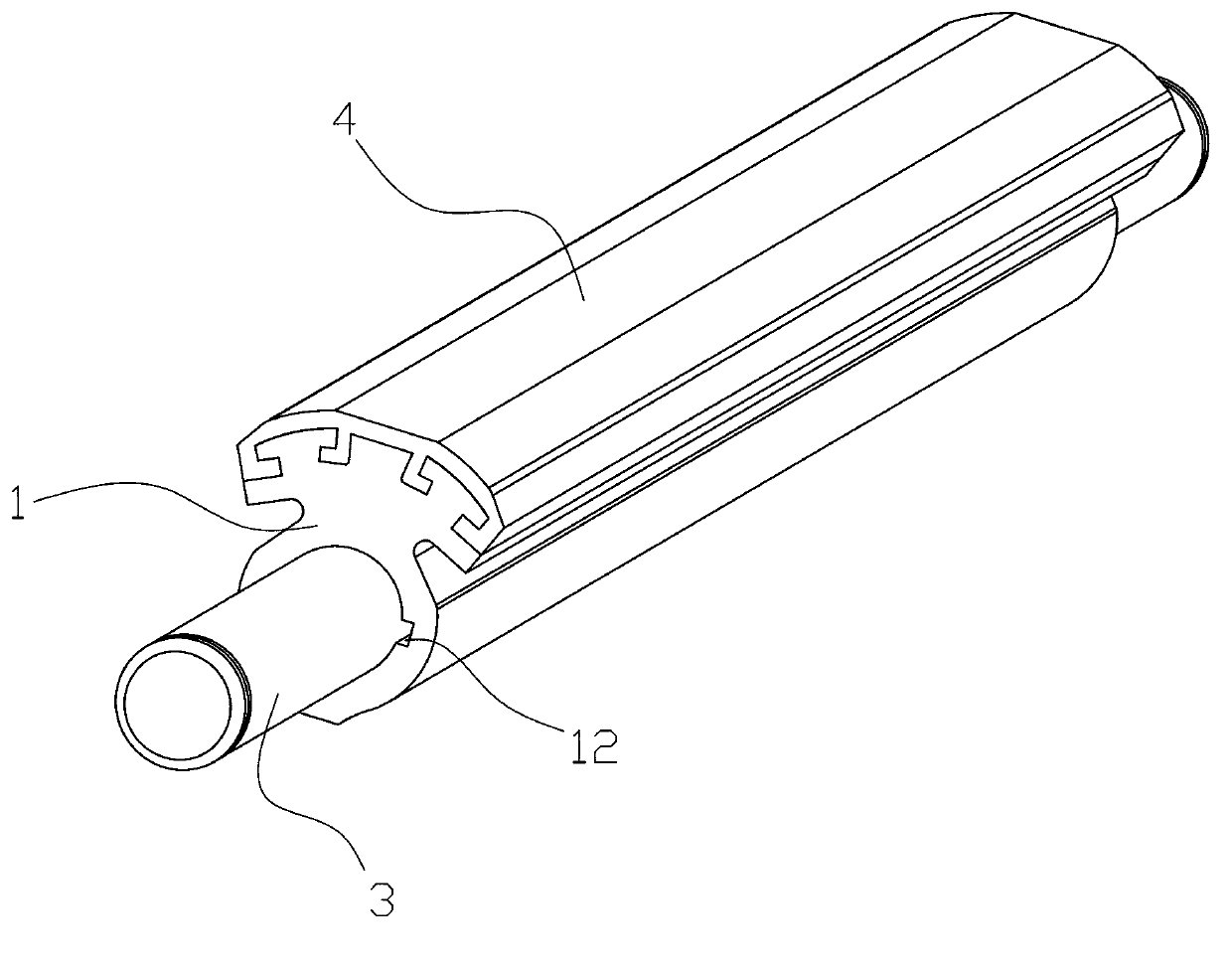
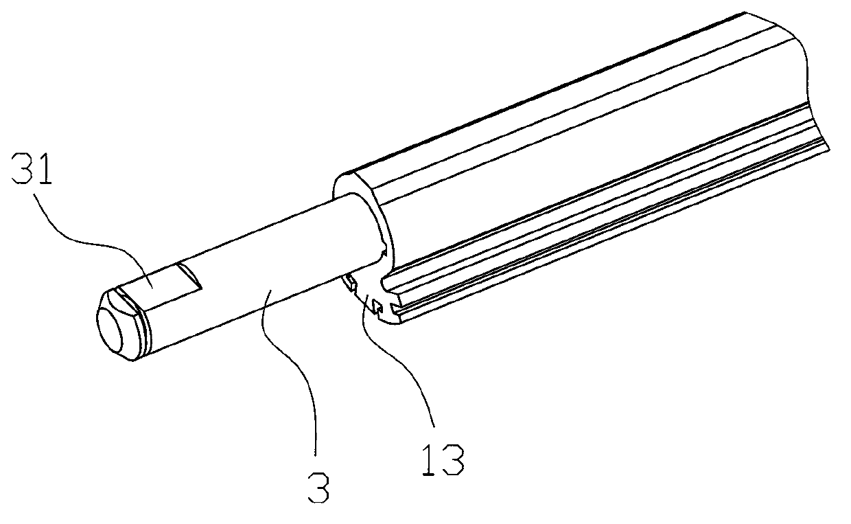
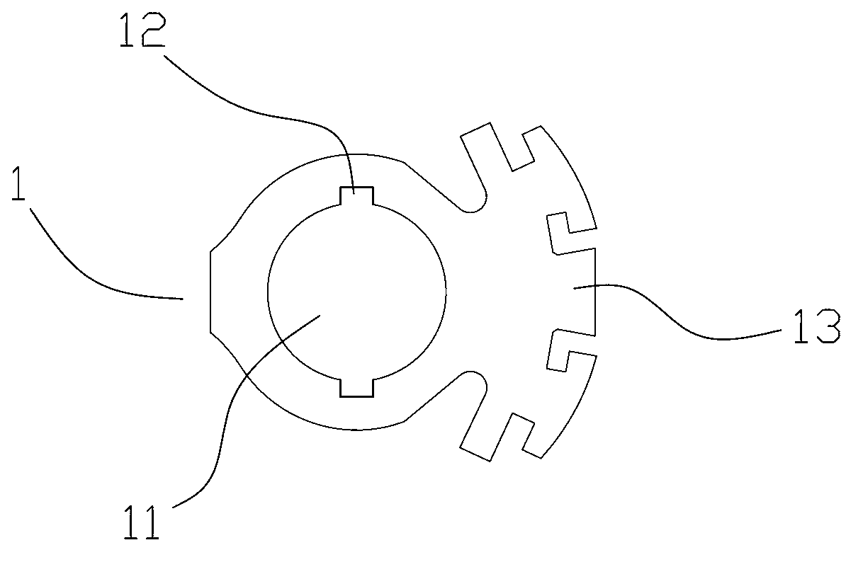
[0016] refer to Figure 1~Figure 3 , a flat printing roller of a dot matrix printer of the present invention, which comprises a support 1, the two ends of the support 1 along its length direction are connected with a support shaft 3 for fixing the support 1 on the printer frame, the support 1 and the support shaft 3 Stainless steel or aluminum alloy materials are used, and shaft holes 11 are preferably provided at both ends of the bracket 1 along its length direction. The support shaft 3 is a round shaft and is interference-fitted in the shaft hole 11 of the bracket 1. The shaft hole 11 There is an exhaust groove 12 along the hole, and the support frame 3 is set as a round shaft to facilitate processing, clamping, inspection, assembly and positioning with high precision. The support shaft 3 is interference fit into the shaft hole 11 of the bracket 1 to ensure that the support shaft 3 and the bracket 1 will not move relative to each other during the working process, and the exh...


PUM


Abstract

The invention discloses a plane surface printing roller of a needle printer, which comprises a bracket, wherein both ends of the bracket along the length direction are connected with a support shaft for mounting and fixing the bracket on the fame of the printer, and an irregular mounting surface is arranged at the tail end of the support shaft; the top of the bracket is provided with a neck part; a flexible glue layer is injected on the neck body; the middle surface of the flexible glue layer is a horizontal surface, and both side surfaces of the flexible glue layer are inclined surfaces. The plane surface printing roller and the frame are convenient and accurate to install and locate; the flexible glue layer is not easy to drop off from the bracket, and the middle surface is the horizontal surface, so that the distances between printing work surfaces and a printing head are the same, the uniformity of ink printed on paper by the printing head is ensured, and the printing quality is improved; moreover, relatively thin thickness of the flexible glue layer can be ensured through the structure, so that only few changes of the printer in a gap between the printing work surfaces and the printing head in a specified temperature range are ensured, and the printing quality under extreme temperature condition can be efficiently improved.

Description

technical field [0001] The invention relates to a plane printing roller of a dot matrix printer. Background technique [0002] For dot matrix printers, a printing roller is usually arranged directly below the printing head, and the printing needle of the printing head falls and hits the printing roller to print ink on the paper. The printing roller in the traditional technology includes a central circular shaft fixed on the printer frame. The central circular shaft is glued and bonded with a full circle of rubber layer. The thickness of the rubber layer generally reaches more than 5mm. During the working process of the printer, the printing The roller is rotating, and the top surface of the printing roller, that is, the printing surface is the circumferential surface of the rubber layer, which makes the distance between the printing surface and the print head unequal, presenting a state of being near the middle and far on both sides, making the printing The ink marks printe...

Claims


Application Information

Patent Timeline
Patent Type & Authority Applications(China)
IPC IPC(8): B41J11/057B41J11/053
Inventor 卢国钊成亚雄李国育梁岐江
Owner KONG YUE ELECTRONICS & INFORMATION IND XIN HUI
Why Eureka
Try Eureka